
Connecting the PICAXE-08 Microcontrller to other Components
The automatic animal feeder circuit utilizes a PICAXE microcontroller as the central control unit. This microcontroller is programmed to monitor the state of a switch, which serves as the input mechanism triggered by the animal. Upon detecting the switch activation, the microcontroller sends a high signal from pin 6 to a relay. The relay acts as an electromechanical switch that closes the circuit to a motor, which is responsible for dispensing food. The motor may be a DC motor or a stepper motor, depending on the design requirements. The food dispensing mechanism can be a simple auger or a rotating plate that releases a predetermined amount of food.
The automatic feeder circuit requires a power supply sufficient to operate both the microcontroller and the motor. Typically, a 5V power supply is adequate for the PICAXE microcontroller, while the motor may require a higher voltage, necessitating the use of a relay that can handle the motor's current rating.
For the house alarm circuit, a similar approach is employed. The circuit must include an input device, such as a PIR (Passive Infrared) sensor or a door/window switch. When the sensor detects motion or the switch is triggered, it sends a signal to the microcontroller. The microcontroller processes this input and activates a relay, which in turn controls a buzzer. The buzzer can be a simple piezoelectric buzzer or a more complex sound-generating device, depending on the desired alarm characteristics.
The schematic for both circuits would include the PICAXE microcontroller, the input switches or sensors, the relays, the motors, and the buzzers, along with appropriate power supply connections and protective components such as diodes across the relay coils to prevent back EMF damage. The layout should ensure that the components are clearly labeled, and connections are logically arranged to facilitate understanding and troubleshooting.The example circuit is for an automatic animal feeder. When the animal pushes the switch the PICAXE microcontroller detects an input. The programme within the microcontroller then outputs at pin 6, energising a relay. This allows a second circuit to turn on a motor, releasing food into the animals dish. Draw a circuit diagram for a simple house al arm. The circuit must have at least one input. An output must activate a relay allowing a second circuit to turn on / off a buzzer. 🔗 External reference
Related Circuits
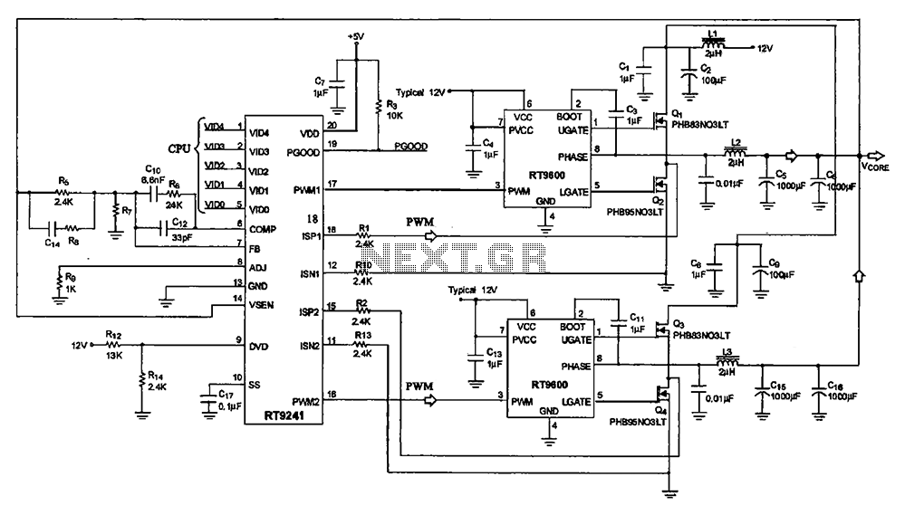
A typical computer motherboard CPU power supply circuit is primarily composed of the main power supply management chip RT9241 and additional components from the power management chip RT9600. The voltage command signal from the CPU is input into the...
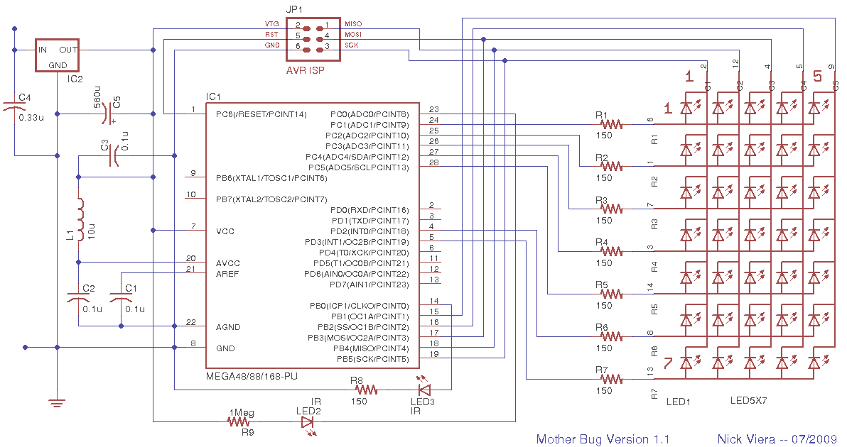
Mother Bug is a simple, interactive electronic message board disguised as a "bug." Text messages are pre-programmed into the memory of the device's microcontroller. When triggered, the microcontroller uses a 5 x 7 LED matrix display to show the...
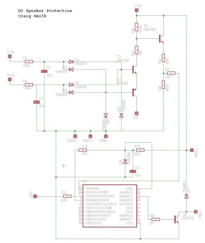
This circuit utilizes schematics from Elliot Sound Products. The left input (L-In) and right input (R-In) are connected directly to the speaker terminals, while the positive and negative voltages are supplied at +25V and -25V from the power supply....
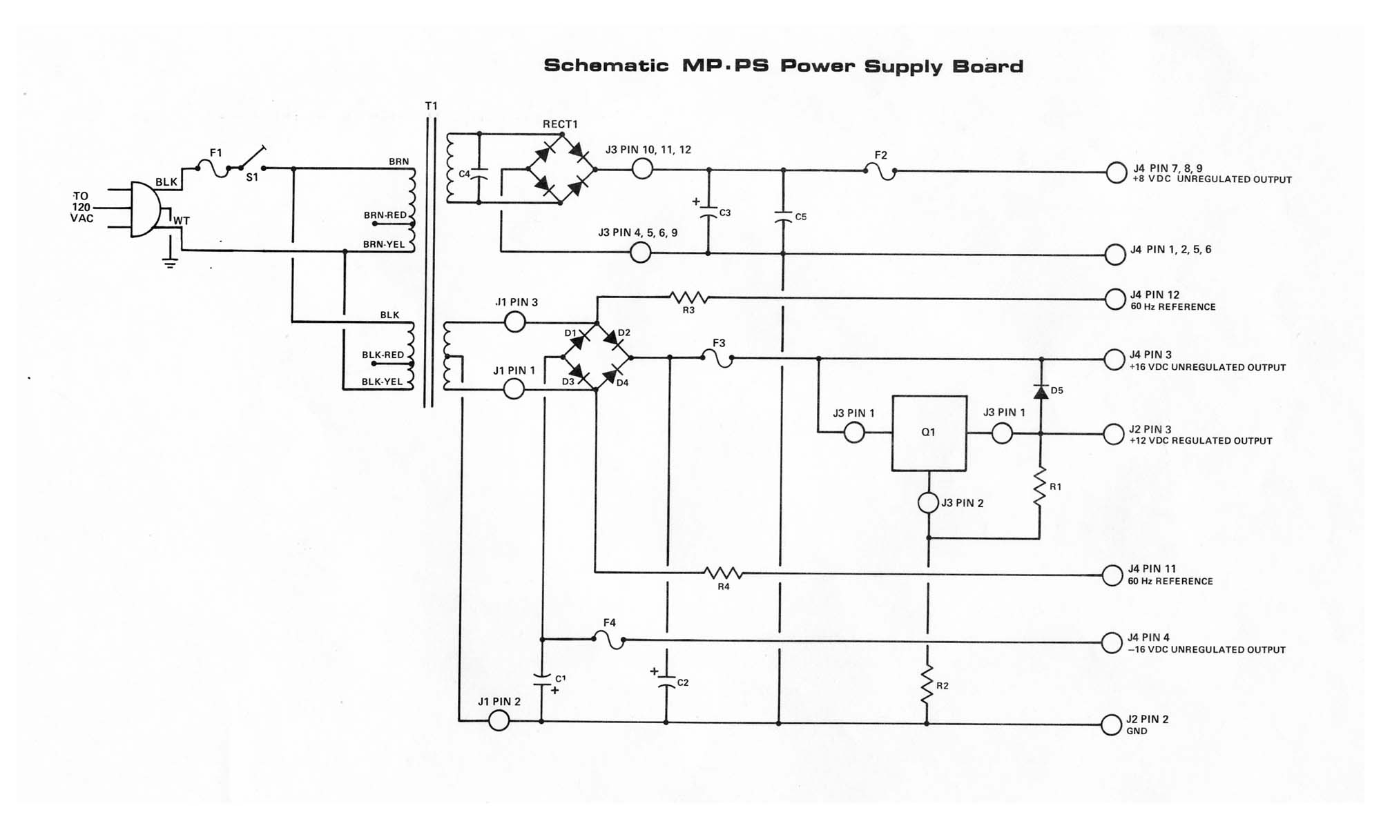
The MP-P2 Power Supply is engineered to provide power to the motherboard and its associated plug-on boards, including the MP-09 Microprocessor Board, disk controller board, memory boards, and up to eight interface boards within the SWTPC Computer system. It...
Where it really shines is in the univibe. The vibe uses a dual section, reverse log taper pot that's just a bit easier to find than a dinosaur's tooth. If we notice that the pot is really wired as...
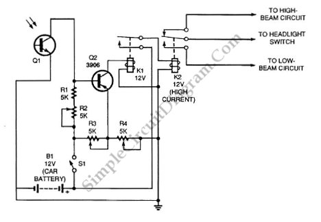
Automatic headlight dimmer circuit diagram for your car's headlight. It ensures safety by providing maximum brightness for the farthest visibility while automatically switching. The automatic headlight dimmer circuit is designed to enhance driving safety by adjusting the brightness of vehicle...
Warning: include(partials/cookie-banner.php): Failed to open stream: Permission denied in /var/www/html/nextgr/view-circuit.php on line 713
Warning: include(): Failed opening 'partials/cookie-banner.php' for inclusion (include_path='.:/usr/share/php') in /var/www/html/nextgr/view-circuit.php on line 713