
A typical computer motherboard CPU power supply circuit
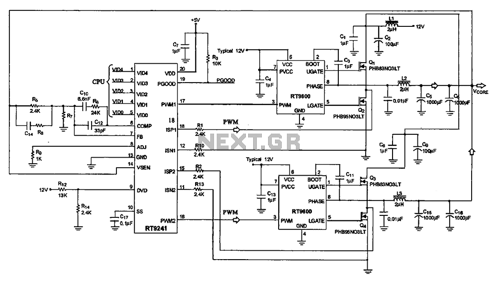
The CPU power supply circuit on a computer motherboard is a critical component designed to ensure stable and efficient power delivery to the processor. The main power management chip, RT9241, plays a pivotal role in regulating the voltage supplied to the CPU. It receives a voltage command signal from the CPU itself, which is essential for dynamic voltage scaling, allowing the processor to adjust its power consumption based on workload demands.
The RT9241 processes this command signal through an internal circuit identification mechanism, which determines the appropriate voltage levels required for optimal CPU operation. It generates two distinct phase PWM (Pulse Width Modulation) signals that are crucial for controlling the power output. The use of two different phases helps in reducing ripple voltage and improving efficiency, as well as enhancing the overall performance of the power supply circuit.
These PWM signals are then routed to the power management components, particularly the RT9600 chip, which further processes these signals. The RT9600 is responsible for driving the external field effect transistors (FETs), specifically Q1, Q2, and Q3. These FETs act as electronic switches that modulate the power delivered to the CPU based on the PWM signals received.
By alternating the states of Q1, Q2, and Q3 in response to the PWM signals, the circuit effectively manages the power flow, ensuring that the CPU receives the necessary voltage and current levels for operation while minimizing energy loss. This arrangement not only supports the CPU's performance but also contributes to the overall power efficiency of the motherboard, which is increasingly important in modern computing environments where energy consumption is a significant concern.
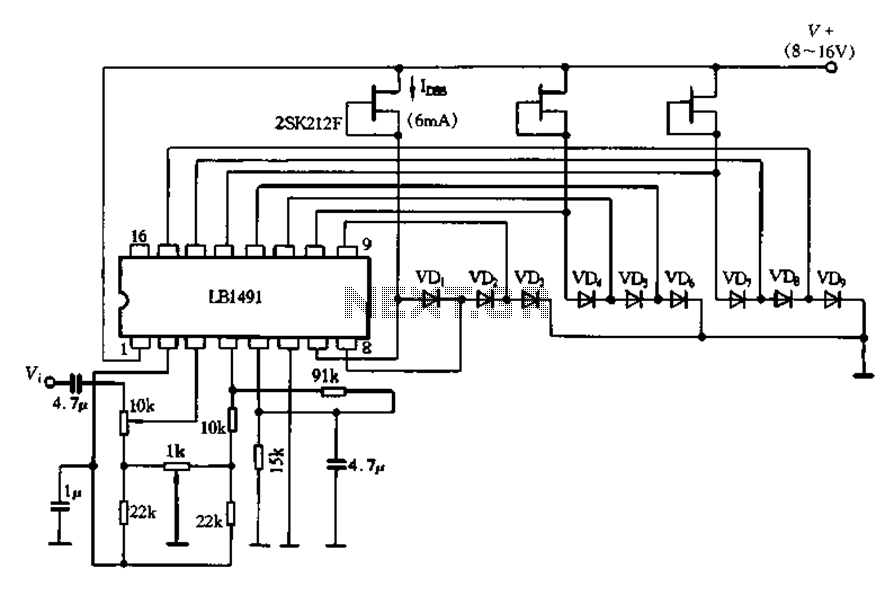
In conclusion, the CPU power supply circuit on a motherboard, utilizing the RT9241 and RT9600 chips, exemplifies a sophisticated approach to power management, ensuring that the CPU operates reliably and efficiently under varying loads.A typical computer motherboard CPU power supply circuit A typical computer motherboard CPU power supply circuit, which is mainly composed of the main power supply management ch ip RT9241, two from the power source management and other parts of the chip RT9600. Voltage command signal from the CPU from the RT9241 O ~ feet into by the chip circuit identification processing, by pin output two different phases PWM pulse signals, respectively, by the two from power management Cang backsheet each output processing of two opposite phase PWM signal, the field effect transistors Qi, Q2 and Q3, Q after power to the CPU.
Related Circuits

The circuit is a rechargeable short delay control for a conducting pipe, featuring two adjustment potentiometers (RP) that enable the delay time to be set from several hundred milliseconds to several seconds. The rechargeable short delay circuit is designed for...
This modified Hartley oscillator can be utilized to attract new friends or serve as a replacement doorbell. The modified Hartley oscillator is a type of electronic oscillator that generates a continuous waveform, typically a sine wave, using an LC (inductor-capacitor)...
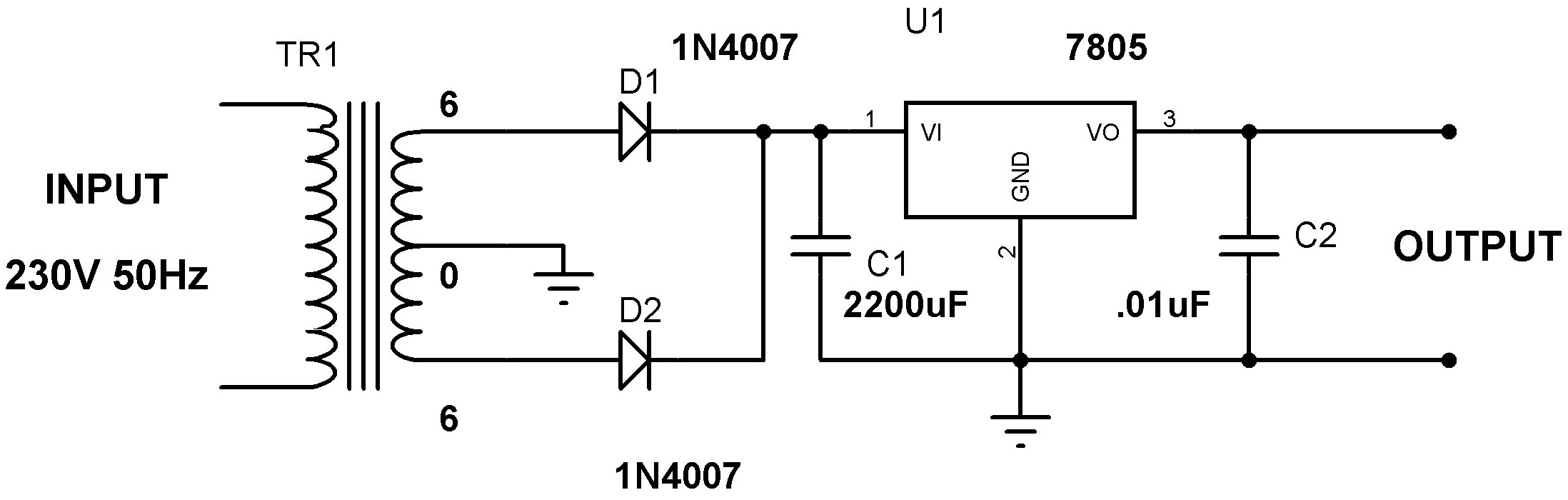
Designing a power supply requires careful consideration of each component. This discussion will focus on the design of a regulated 5V power supply. Note: Any transformer that provides a secondary peak voltage of up to 35V can be used;...
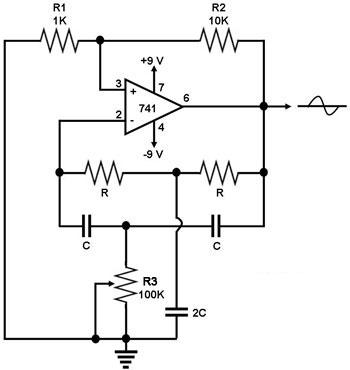
This circuit generates a sine wave using a single operational amplifier (741). The feedback loop of the op-amp includes a twin-T filter connected between its output and inverting input. Positive feedback for oscillation is provided by resistor R2. The...
A display tube utilizing a constant current circuit to ensure a steady flow through the tube. The display tube operates on the principle of maintaining a constant current to achieve consistent brightness and performance. The circuit typically comprises a current...
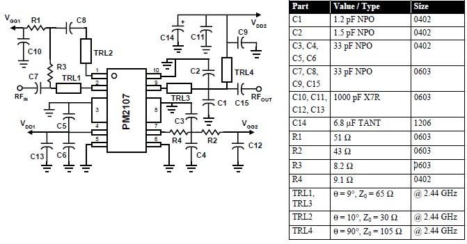
This RFIC amplifier operates in the 2400 MHz ISM band and features a two-stage design that is off-chip matched to ensure optimal performance across various applications. Powered by a 5-volt supply, the PM2107 can deliver 1 watt of saturated...