
connecting voltmeter and ammeter

The voltmeter, ammeter, wattmeter, and energy meter serve as critical tools for the accurate measurement of electrical parameters. Each instrument has its specific function and connection method within an electrical circuit.
The voltmeter is designed to measure the potential difference between two points in an electrical circuit. It is connected in parallel with the component across which the voltage is to be measured. The high internal resistance of the voltmeter ensures that it does not draw significant current from the circuit, preventing any alteration of the circuit's behavior during measurement.
The ammeter, on the other hand, is used to measure the current flowing through a circuit. It is connected in series with the load or component being measured. The internal resistance of an ideal ammeter is zero, which allows it to measure current without affecting the circuit operation.
The wattmeter measures the power consumed by a circuit and is typically connected in parallel with the load while also being in series with the voltage source. It employs two coils: a current coil and a voltage coil. The interaction between these coils allows the wattmeter to calculate the power in watts.
The energy meter, often used in residential and commercial applications, measures the total energy consumed over time. It integrates the power consumption over a specified period and displays it in kilowatt-hours (kWh). The energy meter is connected in series with the load, similar to the ammeter.
Understanding the proper connections and operational principles of these instruments is essential for any electrical engineer. Mastery of these devices enables accurate monitoring and analysis of electrical systems, ensuring their efficient and safe operation.Voltmeter, Ammeter, Watt meter and Energy meter are four pillars of electrical energy and are most important devices used in electrical engineering field. You can`t imagine any application in electrical engineering without voltage, current, energy and power measurement.
Voltmeter, Ammeter, Watt meter and Energy meter connections and basics are discussed here. If you are an electrical engineer than you must know how to connect various electrical instruments in a circuit, Specially measuring instruments. The most common instruments or measuring apparatus you must know about are Voltmeter, Ammeter, Energy meter and Watt meter.
Voltmeter is a device that is used to measure voltage or potential difference across two given points. Essentially a voltmeter is nothing but a galvanometer with infinite resistance connected in series. This makes the resistance of an ideal voltmeter infinite. 🔗 External reference
Related Circuits

The RMS value of a sinusoidal waveform is measured using an average reading voltmeter, which is calibrated to display RMS values. This method is simple and cost-effective. However, when measuring the RMS value of non-sinusoidal waveforms, a true RMS...
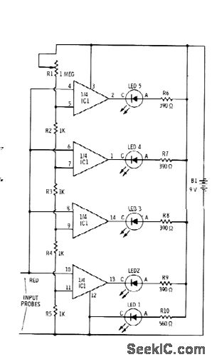
Sections of the RS339 quad comparator each drive an LED to indicate four different input voltage levels. LED 1 is connected to ground to serve as a zero indicator. The resistors depicted are intended for Radio Shack 276-041 red...
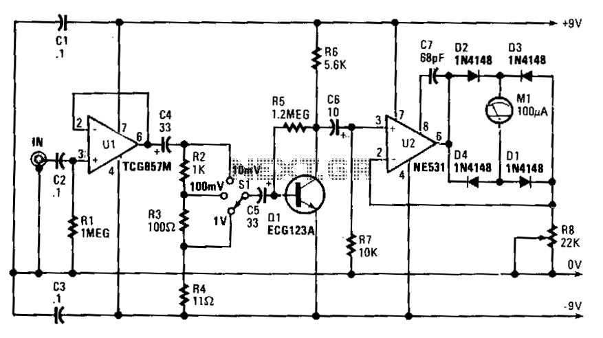
Capacitor C4 couples the output of U1 to a simple attenuator, which provides a loss of 0 dB, 20 dB, or 40 dB, depending on the setting of range switch S1. The circuit's sensitivity is 10 V rms for...
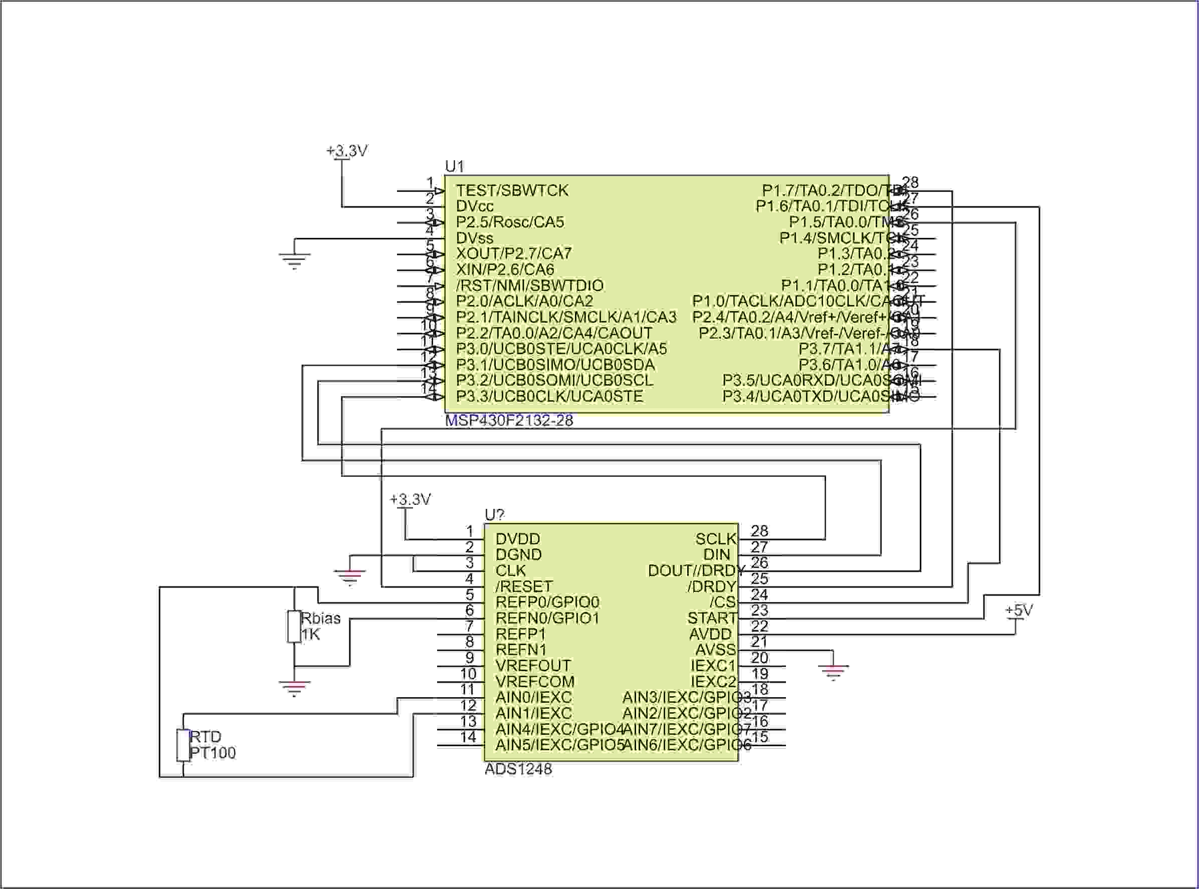
Currently, there is no direct example available for running on IAR. However, assistance is possible to help initiate the process. Clarification is needed on which MSP430 is being used and whether the primary concern is setting up the SPI...
This circuit provides a straightforward method for measuring the voltage of a low-impedance voltage source. It operates as follows: P1, a 1-W potentiometer, acts as a voltage divider in conjunction with resistor R1. The voltage at their junction is...
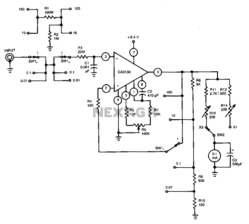
This voltmeter, featuring high input resistance, utilizes a CA3130 BiMOS operational amplifier to measure voltages ranging from 10 mV to 300 V. Resistors R12 and R14 are employed individually to calibrate the meter for full-scale deflection. Additionally, potentiometer R6...