
RMS Reading Voltmeter

In the context of designing a true RMS voltmeter, the circuit typically consists of several key components: an AC amplifier, thermocouples, a DC amplifier, and a PMMC meter. The AC amplifier is crucial for boosting the input signal to an appropriate level before it reaches the heating element of the main thermocouple. This ensures accurate measurement of the heating power generated by the AC signal.
The main thermocouple, which is sensitive to the heating power, converts the thermal energy generated by the input AC signal into a measurable voltage. The balancing thermocouple, placed in the same thermal environment, serves to compensate for any non-linearities in the main thermocouple's response. This arrangement is essential for maintaining measurement accuracy, especially in non-linear waveform scenarios.
The DC amplifier plays a pivotal role in processing the error signal produced when the input waveform is applied. It amplifies this error signal and provides feedback to the balancing thermocouple, adjusting the heating current until the system reaches a balanced state. This feedback mechanism is critical for achieving a stable reading on the PMMC meter.
Moreover, the calibration of the PMMC meter is essential for ensuring that the readings correspond accurately to the RMS values of the input waveforms. The calibration process involves setting the meter to read zero when no input is present and adjusting it to reflect the correct RMS value during operation.
Overall, the design of a true RMS voltmeter is a sophisticated process that combines thermal measurement principles, feedback control systems, and precise calibration techniques to provide accurate RMS voltage readings across a variety of waveform shapes.RMS value of the sinusoidal waveform is meas ured by the average reading voltmeter of which scale is calibrated in terms of rms value. This method is quite simple and less expensive. But sometimes rms value of the non-sinusoidal waveform is required to be measured. For such a measurement a true rms reading voltmeter is required. True rms reading v oltmeter gives a me ter indication by sens ing heating power of waveform which is proportional to the square of the rms value of the voltage. Thermo-couple is used to measure the heating power of the input waveform of which heater is sup plied by the amplified version of the input waveform.
Output voltage of the thermo couple is proportional to the square of the rms value of the input waveform. One more thermo-couple, called the balancing thermo-couple, is used in the same thermal environment in order to overcome the difficulty arising out of non-linear behaviour of the thermo-couple.
Non-linearity of the input circuit thermo-couple is cancelled by the similar non-linear effects of the balancing thermo-couple. These thermo-couples form part of a bridge in the input circuit of a dc amplifier, as shown in block diagram.
AC waveform to be measured is applied to the heating element of the main thermo couple through an ac amplifier. Under absence of any input waveform, output of both thermo-couples are equal so error signal, which is input to dc amplifier, is zero and therefore indicating meter connected to the output of dc amplifier reads zero.
But on the application of input waveform, output of main thermo-couple upsets the balance and an error signal is produced, which gets amplified by the dc amplifier and fedback to the heating element of the balancing thermo-couple. This feedback current reduces the value of error signal and ultimately makes it zero to obtain the balanced bridge condition.
In this balanced condition, feedback current supplied by the dc amplifier to the heating element of the balance thermo-couple is equal to the ac current flowing in the heating element of main thermo-couple. Hence this direct current is directly proportional to the rms value of the input ac voltage and is indicated by the meter connected in the output of the dc amplifier.
The PMMC meter may be calibrated to read the rms voltage directly. By this method, rms value of any voltage waveform can be measured provided that the peak excursions of the waveform do not exceed the dynamic range of the ac amplifier. 🔗 External reference
Related Circuits
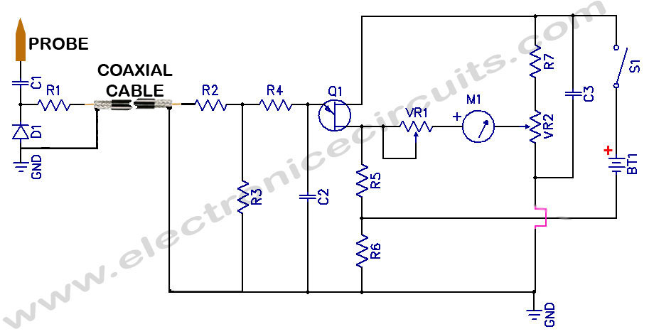
Sensitive RF Voltmeter Probe Circuit. This circuit measures RF voltages beyond 200 MHz and up to approximately 5V. The sensitive RF voltmeter probe circuit is designed to accurately measure radio frequency (RF) voltages in the range exceeding 200 MHz,...
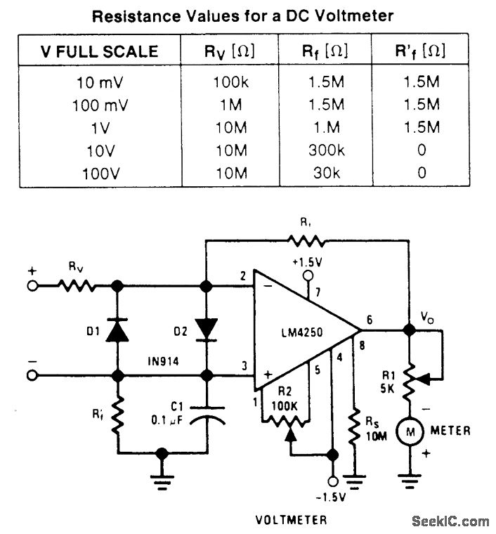
A wide-range voltmeter circuit. This inverting amplifier has a gain varying from -30 for the 10-mV full-scale range to -0.003 for the 100-V full-scale range. Diodes D1 and D2 provide complete amplifier protection for input overvoltages as high as...
This multimeter is designed to measure output voltage and current in a power supply unit (PSU), with the current sense shunt resistor connected in series with the load at the negative voltage rail. It operates using a single supply...
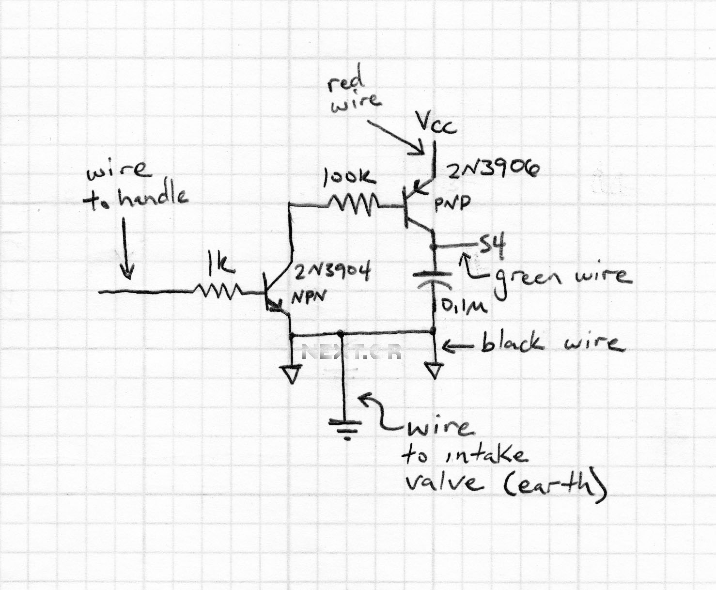
This document was created to address the numerous inquiries received about how to read a schematic. Learning to interpret a schematic diagram is akin to map reading; it requires understanding which wires connect to which components and identifying the...
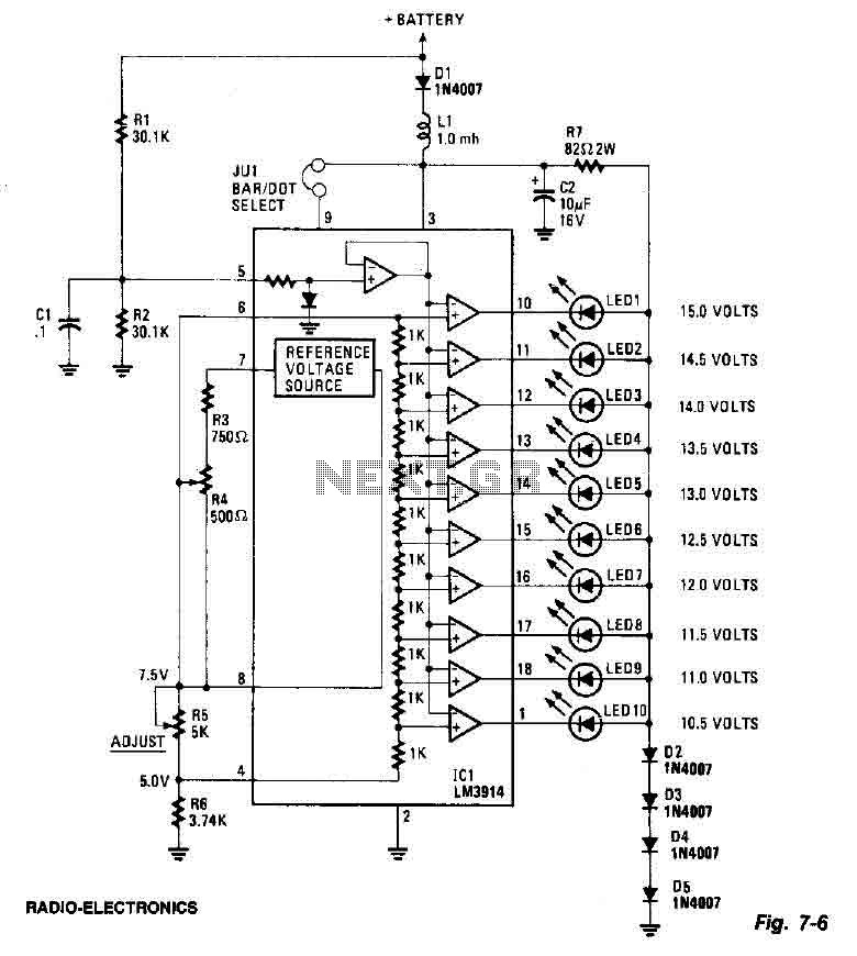
This screen utilizes ten LEDs to indicate a voltage range from 10.5 to 15 volts, with each LED corresponding to a 0.5-volt increment. The core component of the circuit is the LM3914 LED bar graph/display driver. A trimming potentiometer,...
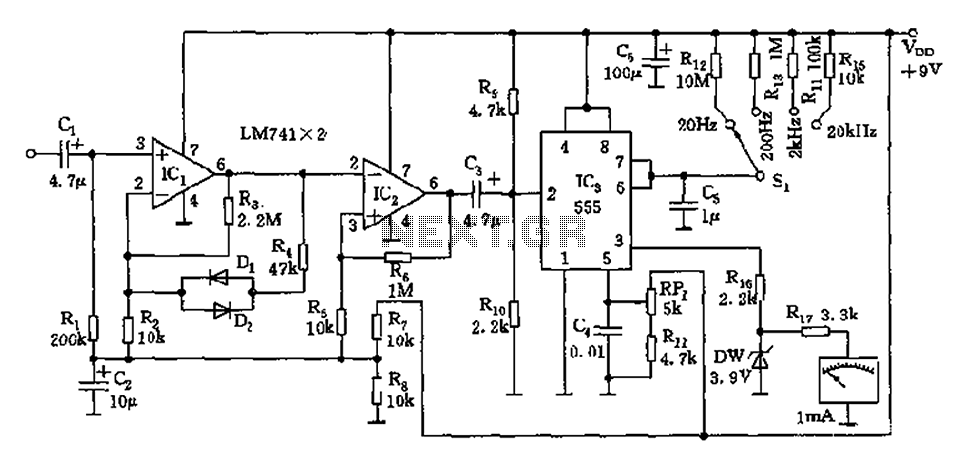
The circuit is a direct-reading frequency meter that utilizes an amplifier and a one-shot trigger circuit, along with table-top components. It is capable of directly detecting a 1mA signal at the read head, with a maximum signal frequency of...