
Connection Tester
The continuity tester circuit described utilizes a 741 operational amplifier (op-amp) configured in a differential mode to detect low resistances typically found in soldered joints and connections. The operational amplifier's differential input allows for the measurement of small voltage differences, which are indicative of continuity in the circuit being tested.
In the absence of any applied resistance, the circuit is designed such that the voltage difference between the non-inverting (+) and inverting (-) inputs of the op-amp is ideally zero. Under these conditions, the output of the op-amp remains at zero volts. However, the introduction of a 470kΩ resistor and a 10kΩ potentiometer serves to create a small imbalance in the input voltages. This imbalance is crucial as it allows for the detection of low resistance values.
When a low resistance (between 0.25Ω and 4Ω) is present across the test leads, it generates a slight voltage difference that is amplified by the op-amp's open-loop gain. The output of the op-amp will then swing towards the supply voltage, which can be used to drive an indicator, such as an LED. The LED acts as a visual indicator of continuity, lighting up when a connection is established.
The selection of the 470kΩ and 10kΩ components is essential for adjusting the sensitivity of the circuit. The potentiometer can be calibrated to fine-tune the threshold at which the LED will illuminate, allowing for flexibility in testing various types of connections and solder joints. This simple yet effective circuit design provides an efficient means of verifying electrical connections, ensuring reliable performance in electronic assemblies.A low resistance ( 0.25 - 4 ohm) continuity tester for checking soldered joints and connections. This simple circuit uses a 741 op-amp in differential mode as a continuity tester. The voltage difference between the non-inverting and inverting inputs is amplified by the full open loop gain of the op-amp. Ignore the 470k and the 10k control for the moment, and look at the input of the op-amp. If the resistors were perfectly matched, then the voltage difference would be zero and output zero. However the use of the 470k and 10k control allows a small potential difference to be applied across the op-amp inputs and upset the balance of the circuit. This is amplified causing the op-amp output to swing to full supply voltage and light the LED' 🔗 External reference
Related Circuits
This circuit utilizes the widely available and user-friendly LM3914 integrated circuit (IC). The LM3914 is straightforward to operate, does not require external voltage regulators due to its built-in voltage regulation, and can be powered by nearly any voltage source....
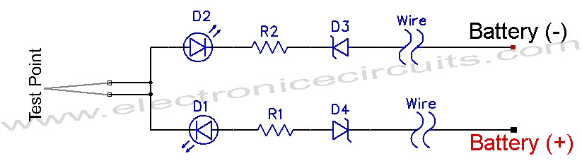
12V Vehicle Electrical Wiring Tester Circuit. This tester is useful for checking vehicle electrical circuits. Two LEDs indicate whether the circuit is live or not. The 12V vehicle electrical wiring tester circuit is designed to provide a simple yet effective...
Liquid crystal displays (LCDs) are available in various versions and sizes. The wide variety of features has led to some confusion regarding pin configurations. Consequently, even after extensive searching for a suitable screen, users often encounter difficulties in utilizing...

This circuit utilizes the widely available LM3914 integrated circuit (IC). The LM3914 is straightforward to operate, does not require external voltage regulators due to its built-in voltage regulation, and can be powered from nearly any voltage source. This makes...
This project utilizes a microcontroller that is programmed with software available on the Gernsback BBS at 516-293-2283 as part of RUNABOUT.ZIP. The robot can be operated using a universal remote control. The project involves the integration of a microcontroller, which...
With this tester you can check whether a diode is working properly. In the table you can see what LED to indicate the positions of the switch and condition of the diode. The circuit can be connected to a...
Warning: include(partials/cookie-banner.php): Failed to open stream: Permission denied in /var/www/html/nextgr/view-circuit.php on line 713
Warning: include(): Failed opening 'partials/cookie-banner.php' for inclusion (include_path='.:/usr/share/php') in /var/www/html/nextgr/view-circuit.php on line 713