
Simple but reliable car battery tester
The LM3914 IC is a versatile device designed for voltage level indication and can operate in either bar graph or dot mode. In this circuit, the high-impedance voltage divider plays a critical role in ensuring that the input voltage is accurately scaled down to a manageable level for the IC to interpret. The internal architecture of the LM3914 consists of a series of comparators that activate the corresponding LED indicators based on the input voltage levels. The precision resistors within the IC ensure that the output is consistent and reliable.
The choice of a 4700µF smoothing capacitor is significant, as it helps to stabilize the voltage readings by filtering out transient spikes that may occur when the engine is running. This is particularly important in automotive applications, where the electrical environment can be noisy due to various components such as the ignition system. The capacitor's voltage rating of 16V provides an adequate safety margin above the maximum expected input voltage.
For applications requiring flexibility in voltage measurement, the offset trimmer allows for customization of the lower limit of the measurement range. By setting the offset to zero, the circuit can measure voltages as low as 0V, which can be useful for diagnostic purposes. However, it is important to consider the operational limits of the vehicle, as voltages below 9V may indicate a battery that is not in optimal condition for starting the engine.
Overall, this circuit offers a practical solution for monitoring automotive battery voltage, providing clear visual feedback through LED indicators while ensuring accuracy and stability across a range of operating conditions.This circuit uses the popular and easy to find LM3914 IC. This IC is very simple to drive, needs no voltage regulators (it has a built in voltage regulator) and can be powered from almost every source. When the test button is pressed, the Car battery voltage is feed into a high impedance voltage divider.
His purpose is to divide 12V to 1, 25V (or l ower values to lower values). This solution is better than letting the internal voltage regulator set the 12V sample voltage to be feed into the internal voltage divider simply because it cannot regulate 12V when the voltage drops lower (linear regulators only step down). Simply wiring with no adjust, the regulator provides stable 1, 25V which is fed into the precision internal resistor cascade to generate sample voltages for the internal comparators.
Anyway the default setting let you to measure voltages between 8 and 12V but you can measure even from 0V to 12V setting the offset trimmer to 0 (but i think that under 9 volt your car would not start). There is a smoothing capacitor (4700uF 16V) it is used to adsorb EMF noise produced from the ignition coil if you are measuring the battery during the engine working.
Diesel engines would not need it, but i`m not sure. If you like more a point graph rather than a bar graph simply disconnect pin 9 on the IC (MODE) from power. The calculations are simple (default) 🔗 External reference
Related Circuits
A battery-status indicator circuit is useful for monitoring portable test equipment and similar devices. LED D1 flashes to attract the user's attention, signaling that the circuit is operational, preventing it from being left on unintentionally. The circuit produces approximately...
Several schematic drawings of battery charger circuits are provided. These circuits cover 5W to 200W for NiCd, NiMH, Lead-Acid, Li-Ion/Polymer, and LiFePO4 battery packs. The charger circuit files aim to assist users in selecting the appropriate chargers and to...
This design will appeal to technicians working with pneumatically operated valves and other devices controlled by a 4-20mA current loop. While 4-20mA signal injectors and calibrators are available, this particular model is cost-effective to construct and user-friendly. Upon initial...
This circuit provides a straightforward method for measuring the voltage of a low-impedance voltage source. It operates as follows: P1, a 1-W potentiometer, acts as a voltage divider in conjunction with resistor R1. The voltage at their junction is...
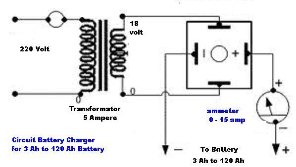
The circuit diagram of a simple and straightforward 12 V battery charger is presented here. This circuit can be utilized to charge various types of 12V rechargeable batteries, including car batteries and motorcycle batteries. The 12 V battery charger circuit...
In certain situations, it is beneficial to enhance the range of available control, and this circuit serves that purpose by receiving the infrared (IR) signal from a remote control and re-transmitting it, potentially around corners or into other rooms....
Warning: include(partials/cookie-banner.php): Failed to open stream: Permission denied in /var/www/html/nextgr/view-circuit.php on line 713
Warning: include(): Failed opening 'partials/cookie-banner.php' for inclusion (include_path='.:/usr/share/php') in /var/www/html/nextgr/view-circuit.php on line 713