
Diode Tester schematic

The described circuit functions as a diode tester, utilizing a straightforward design to determine the operational status of various diodes. The circuit is powered by a 9 V battery, which provides the necessary voltage for testing.
The primary components include resistors, diodes, and transistors. Resistors R1 and R6, both rated at 1 kOhm, are likely used to limit current through the circuit, ensuring that the LED (D1) operates within safe parameters. R2, a 100 kOhm resistor, may serve as a pull-down or pull-up resistor, depending on its connection within the circuit, to stabilize the voltage levels when the switch is not engaged.
Resistors R3, R5, and R7, each rated at 22 kOhm, are likely used in conjunction with the transistors T1 and T2 (BC548) to control the switching mechanism of the tester. The BC548 transistors are NPN types, which are commonly used for switching and amplification purposes. They may be configured in a way to enhance the sensitivity of the tester, allowing for the detection of diode functionality through the LED indication.
R4, valued at 2.2 kOhm, likely serves a similar purpose as the other resistors, possibly providing additional current limiting or feedback within the circuit.
The LED (D1) acts as an indicator, illuminating when the diode under test (D2) is functioning correctly. The circuit may include a switch that allows users to select different test modes or conditions, as indicated by the table mentioned in the description. This switch configuration is essential for providing clear feedback on the state of the diode being tested.
In summary, this circuit is a practical tool for testing diodes, employing a combination of resistors, transistors, and an LED to provide visual feedback on the operational status of the diode. The design is efficient and straightforward, making it suitable for both educational purposes and practical applications in electronics troubleshooting.With this tester you can check whether a diode is working properly. In the table you can see what LED to indicate the positions of the switch and condition of the diode. The circuit can be connected to a 9 V battery. R1, R6 = 1 kOhm R2 = 100 kOhm R3, R5, R7 = 22 kOhm R4 = 2.2 kOhm D1 = LED D2 = Diode test T1, T2 = BC548 🔗 External reference
Related Circuits

This is a simple and low-cost NiCd and NiMH battery charger. The schematic diagram indicates that the charging current (I) should be set to 1/10 of the battery's rated capacity. For instance, if the battery has a rated capacity...
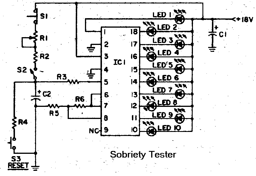
With all the holidays upon us, understandably some of us will be drinking alcoholic beverages. This circuit can be used as a guideline how much you have had to drink and how good your reaction time is. This circuit...
A small bias on the bases of Q1 and Q2 through R1 and R2 assists in initiating the circuit. This provides each transistor's base with a slight forward bias, enabling both transistors to conduct when the circuit is initially...
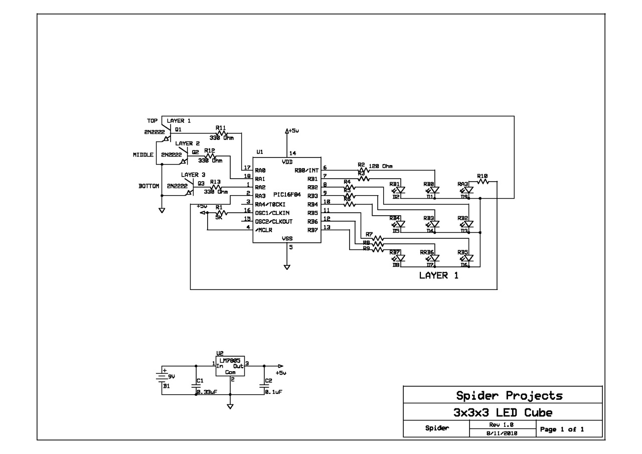
This schematic was sourced from the Internet and utilized for a prototype cube. The schematic only depicts the first LED layer, requiring the user to independently construct up to the third layer. A single current limiting resistor is employed...
This circuit can be used to charge accumulator and cell batteries. It features a very stable output that extends the battery life and maximizes the added battery capacity. The charging process is also quite fast, optimizing the time required...
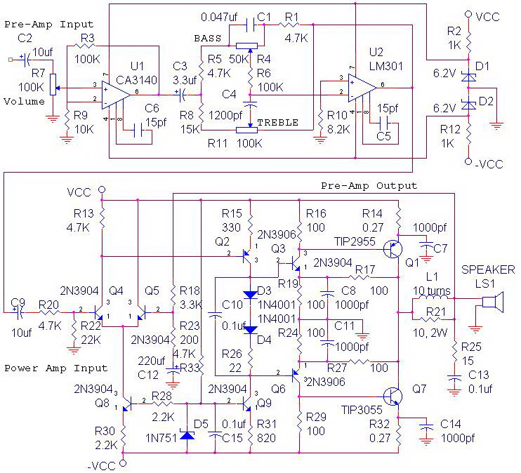
The circuit power amplifier depicted is a schematic design for a power amplifier with an output power of 70 watts, operating in Class AB mode. This power amplifier circuit is equipped with a tone control circuit. The 70-watt power...