
continuity tester circuit
The continuity tester circuit is an effective tool for various applications, including educational demonstrations and practical uses in electronics. The design leverages the simplicity of a one-transistor switch, ensuring that the circuit remains compact and efficient. The integration of a musical component adds an engaging auditory feedback mechanism that enhances user interaction. Furthermore, the use of banana sockets allows for easy connectivity and adaptability to different probes, making it suitable for diverse testing scenarios. The circuit's sensitivity to moisture makes it a valuable asset for environmental assessments, while its educational potential provides a hands-on learning experience for students in understanding circuit principles. Overall, this continuity tester circuit exemplifies a practical and versatile design in electronics engineering.A continuity tester is handy for checking that there is a conducting path between two points. The following circuit has the advantage that it is very sensitive and it gives both a visual and audible indication of continuity. An audible tester is handy since you are normally looking at where you are placing the tester contacts rather than looking a
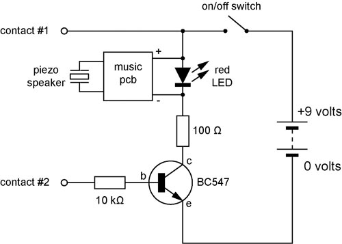
t the tester itself. The circuit diagram shows that the continuity tester is made up of a sensitive one-transistor switch which turns on a LED and a circuit taken from a musical greeting card. Most greeting card circuits are powered by a single 1. 5 volt "hearing aid" cell so I have connectedthe music printed circuit board (pcb) across the red LED which maintains a fairly constant voltage of 1.
5 volts across it. Some musical circuits use two cells so you could change the LED to a green, blue or white one which would increase the voltage across the pcb. The base resistor value is not critical. I have specified 10 k © here but its purpose really is only to limit the maximum current that can pass through the base-emitter part of the transistor.
A value of 100 k © seems to work just as well. Again the collector resistor (100 ©) is not too critical. Higher values will limit the current through the music pcb and LED making the music quieter and slower. The music`s pitch may may also be affected a little. Two musical greeting card pcbs and their piezo speakers are shown in the picture below. The one on the left is unmodified and has its cell, cell holder and off/on switch still attached. These have been removed from the pcb on the right. The photo below shows the components soldered together. The contacts used here are connected to 4 mm "banana" sockets. This makes the circuit more versatile since a range of probes or connectors can be attached to the sockets.
Below are two views of the finished musical continuity tester in its box. The piezo speaker leads were unsoldered from the pcb and fed through two small holes drilled into the box before being soldered back onto the pcb. The red LED is glued to the box and attached by flying leads to the pcb. The banana sockets are attached on either side of the box. As a moisture tester. This circuit is sensitive enough to operate when the two contacts are placed in damp soil or on a damp wall.
Your skin is moist enough to trigger the circuit - see the next use. To demonstrate to students that components need to be connected in a closed loop for a circuit to work. Get a class of students to form a circle and hold hands. Get two adjacent volunteers - one to hold the tester in such a way that their index finger touches one socket/contact.
The other volunteer touches just the other socket/contact (making sure not to touch the first volunteer). Once all are holding hands and the music is playing I point to various partners to momentarily break from holding hands - the music stops and then resumes when they hold hands again.
I also make sure the students realise they are "connected" together in a series circuit. As the base circuit for a game of skill like "operation". A wiggly length of rigid wire (florist`s wire or a bent coat hanger) is connected to one socket. A small wire loop is attached to the other socket using a flexible wire lead. The aim of the game is to move the loop along the wiggly wire without touching it and setting off the music. 🔗 External reference
Related Circuits

This is a circuit design for a PWM speed control circuit for DC motor rotation. The circuit features two functions: Forward-Reverse operation and Regenerative Braking. The control is achieved using a MOSFET. The circuit allows for the control of...
This circuit is designed to dim lights with a maximum capacity of approximately 350 watts. It employs a standard TRIAC circuit configuration, which has been observed to generate minimal heat during operation. It is important to note that this...

One type of tone regulator is the audio graphic equalizer, which can be categorized into two types: the audio graphic equalizer bar and the parametric equalizer. This article focuses on the bar type, specifically a 5-channel equalizer utilizing the...

This project involves a compact, portable DJ mixer that can be powered by a 9V DC external supply adapter or a 9V PP3 battery. The mixer includes two stereo phono inputs, two stereo line-level inputs, and a single stereo...
Solar battery charger schematic and description. This solar battery charger circuit is capable of charging a 12V lead-acid battery or sealed lead-acid (SLA) battery. The solar battery charger circuit is designed to convert solar energy into electrical energy for charging...
How many speakers can be attached to this amplifier, and what are the impedance and wattage values of these speakers? Please respond to my email. Sir, you made this amplifier, and it works properly for a lifetime. Which transformer...
Warning: include(partials/cookie-banner.php): Failed to open stream: Permission denied in /var/www/html/nextgr/view-circuit.php on line 713
Warning: include(): Failed opening 'partials/cookie-banner.php' for inclusion (include_path='.:/usr/share/php') in /var/www/html/nextgr/view-circuit.php on line 713