
Control an Amplifier With a SqueezeBox
This project aims to utilize the power supply of the Squeezebox to power the amplifier while detecting the Squeezebox's state through its Toslink (SPDIF) optical output. A mains relay is employed to control the amplifier's power. Additionally, the Squeezebox's coaxial digital output may be used instead of the optical output, and an "optical pass-through" could be implemented for users wishing to maintain the optical output functionality. The circuit is capable of controlling two relays, although only one is depicted in the accompanying diagrams. The first relay manages the amplifier's power, while the second can disconnect the speakers to prevent "switching bang," a noise issue encountered with some lower-quality amplifiers during power cycling.
The Toslink signal is challenging to decode; however, this project focuses on the carrier signal to determine the Squeezebox's state. The Toslink signal operates at a carrier frequency of 1413 kHz while the player is on, dropping to 1323 kHz when off. During playback, the carrier frequency fluctuates, typically reaching around 1700 kHz, independent of volume or music type. This frequency variation can be measured with a frequency counting multimeter or an appropriately configured Arduino. The Arduino functions as a frequency counter, regularly checking the carrier signal frequency to control a relay that switches the amplifier's mains power.
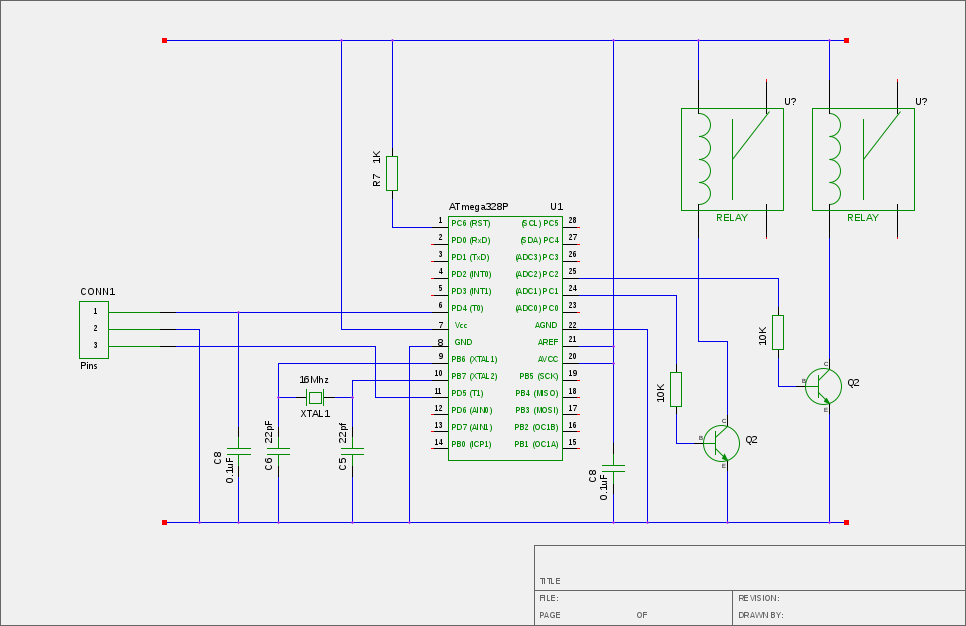
Since the Arduino cannot directly operate the relay, a transistor is utilized to facilitate this function. The optical receiver in the circuit is a powered device operating at 5V with a TTL-compatible output (though the signal edges may not be perfectly square). This output is connected to the Arduino, specifically to digital pin 5 (physical pin 11), as it is the only pin linked to counter/timer 1. By allowing the counter to increment based on the optical input, the frequency of the incoming signal can be calculated over a designated time interval. To conserve power, the optical receiver is powered by the Arduino, and the frequency is read intermittently, allowing the receiver to enter a power-saving mode when not in use. While this approach reduces power consumption, it is not strictly necessary, and the optical receiver could be powered continuously if desired.
The overall design emphasizes a seamless integration of the Squeezebox and amplifier, enhancing user convenience while minimizing hardware modifications and maintaining operational integrity.If you`ve got a Squeezebox then you`ve probably got an amplifer to go with it. Having to get up and turn the amp on and off when you need it is just far too tedious (especially if your Squeezebox is hidden away in a cupboard or something), so we need a gadget that can turn the amp on when the Squeezebox turns off, and turns the amp off again whenit turns off. Sounds pretty simple, right There are a few other attempts to do this around the Internet. There`s a server module called PowerCenter that can send commands via a serial port to and X10 sender. The X10 signals then control plug-in X10 modules on the amplifer power cord. This sort of approach works well, but needs quite a bit of X10 hardware to make it work. There`s a DIY hardware hack that uses a sensor on the front panel LED of a Duet Receiver to detect if the player is on or off.
This particular hack uses power from inside the Receiver, and of course only works with a Duet. As it happens, my particular concern is with a Duet, but I`d rather not have to crack open the case and fit some dangling wires out of it. So with all that in mind, this project uses the Squeezebox`s power supply for it`s power source, and passes that power on to the player (it should work with most of the modern Squeezebox models too - not quite with the Squeezebox 1 though - see below).
It uses the Toslink (SPDIF) optical output of the Squeezebox as the means of detecting the players state, and it uses a mains relay to switch the amp on and off. It`s possible to use the Squeezebox`s coaxial digital output if you don`t want to use the optical, or it could have an "optical pass through" if you still want to use the optical output.
The actual electronics can control two relays (the second isn`t used in the pictures below though). The idea is that you can use one relay to control the amp power and the other to switch the speakers in or out. This can be used to avoid "switching bang" that some cheap amps suffer from when they turn on or off.
The second relay essentially disconnects the speakers from the amp until the "bang" has subsided. Toslink is pretty difficult to decode and use. Instead of trying to do that, this project looks at the carrier signal and uses that to work out the state of the player. It turns out that Toslink uses a 1413Khz carrier signal, which is running the whole time the player is on.
However, if the player is off, that carrier frequency drops to 1323KHz. When the player is actually playing music the carrier frequency isn`t stable, but it`s usually up at about 1700Khz, and it doesn`t seem to matter what the volume is or what type of music is playing. This is all detectable with a frequency counting multimeter, and also with a suitably setup Arduino. The Arduino in the circuit acts as a frequency counter which periodically checks the carrier signal frequency.
From that, it controls a relay, which switches the mains power to the amp on and off. The Arduino can`t switch the relay directly, so we use a transistor to actually switch the relay. The circuit diagram is shown below. The optical receiver is a powered device which operates at 5V. It`s output is TTL compatible (although it`s edges aren`t necessarily square), so we just connect the output to the Arduino. We have to use Arduno digital pin 5 (physical pin 11) for the optical input (this isn`t configurable) because it`s the only pin connected to counter/timer 1.
By letting the counter be incremented by the optical, we can count how many increments there were in a set time, and so work out the frequency of the incoming signal. As a power saving measure, we power the optical receiver from the Arduino. When we look at the code, we`ll see that we only read the frequency of the signal every so often, so for the rest of the time we can power-down the receiver.
This saves us a few milliamps, but isn`t strictly necessary (so you could permanently power the optical reciever 🔗 External reference
Related Circuits
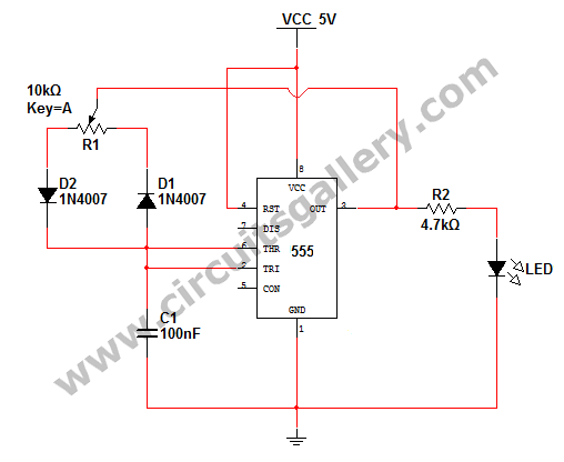
How to change the brightness of an LED. Are LED lights dimmable? Is it possible to adjust the brightness of LEDs? An LED is essentially a diode; when the forward voltage exceeds 0.7 volts, it begins to emit light,...
The LM231 and LM331 family of voltage-to-frequency converters are well-suited for use in simple, low-cost circuits designed for analog-to-digital conversion, precision frequency-to-voltage conversion, long-term integration, linear frequency modulation or demodulation, and various other applications. When utilized as a voltage-to-frequency...
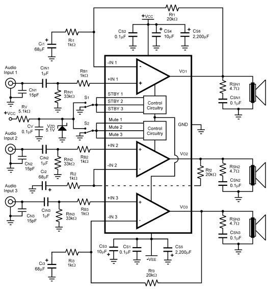
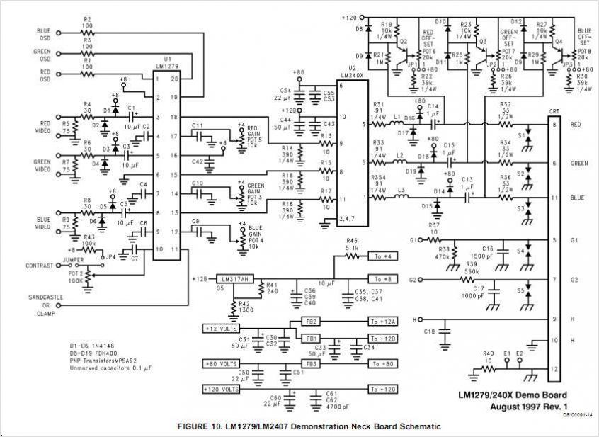
The LM4782 utilizes a protection system known as National Self Peak Instantaneous Temperature (Ke) (SPiKeTM). SPiKe safeguards the output of the LM4782 against over-voltage on the load, short circuits to ground, and provides temperature protection by monitoring instantaneous temperature....
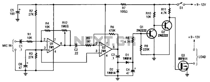
This audio-controlled switch integrates a pair of 741 operational amplifiers, two 2N2222 general-purpose transistors, an hcxFET, and several supporting components into a circuit capable of activating devices such as a tape recorder, a transmitter, or virtually any sound-activated equipment. The...
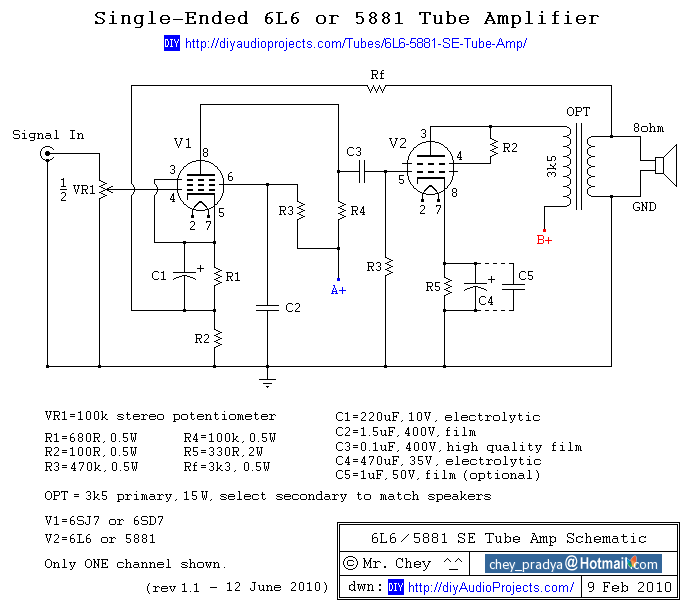
This past summer, an inspiration arose from watching "Transformers: Revenge of the Fallen" to construct an enclosure for a vacuum tube amplifier featuring the Decepticon logo. The tube amplifier replaces a solid-state amplifier that was driven by a tube...
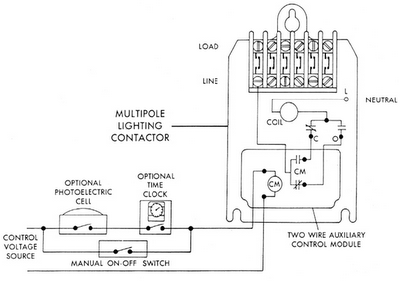
Sensors for lighting controls include photoelectric sensors and presence detectors. Photoelectric sensors typically switch lighting on at dusk and off at dawn, with adjustable settings for sensitivity to light levels. They feature built-in time delays to prevent unwanted switching...