
Lighting Control
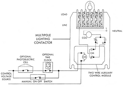
Today's industrial computer and programmable controller (PLC)-based control systems are advanced versions of electronic timers. Central to these systems is an industrial computer or PLC that stores a series of on-off commands for the lighting circuits throughout a facility. These systems enable minute-by-minute control of the entire lighting setup based on a user-defined schedule, utilizing pulse initiation from an internal clock. Inputs from photo sensors, occupancy sensors, and manual controls help inform the control decisions. The control signals can be transmitted throughout the building using twisted pair communication wires, or through existing power lines to the receiver control modules. To allow command signals to bypass transformers without direct copper connections, couplers are utilized. The controller's codes are sent to transceivers, which may merge them with other signals before relaying them to the lighting contactors. These contactors often incorporate low-voltage control modules that can be directly operated by the controller's output. Programming for discretionary control and override functions can be visualized on a CRT or operator interface graphic display, with options for hard copy printing. A conceptual scheme for an industrial computer/PLC-based lighting control system illustrates these functionalities and connections.Sensors for lighting controls are either photoelectric sensing or presence detectors. Photoelectric sensors are normally set to switch lighting on at dusk and off at dawn. Adjustments can be made to change response to higher or lower levels. Built-in time delay helps to eliminate nuisance switching in response to sources other than natural ambient light, or passing shadows. Photoelectric sensors are often combined with timers to provide a more efficient light control. Figure 12 shows such a control arrangement. Contacts on both photoelectric switch and the timer must close to cause the multi-pole lighting contactor to switch on the lights. Opening either set of contacts will open the lighting contactor, thus turning off the lights. A typical application would be an industrial parking lot where lighting is required only Monday through Friday evenings, and is turned on at dusk and shut off at midnight.
The two-wire control may be a separate electromagnetic control relay or a built-in control module as shown. A variety of presence detectors or occupancy sensors have been recently developed. These detectors automatically activate the lighting controls. They are designed to turn lights on upon sensing heat or motion caused by human occupancy within a defined space and turn them off at some preset time after the last person leaves.
PART II. Todays industrial computer and programmable controller (PLC) based control systems are sophisticated versions of electronic timers. The heart of such a system is an industrial computer and/or PLC-based controller that holds in memory a series of on-off instructions to the lighting circuits throughout a building.
They can provide minute-by-minute control of an entire lighting scheme according to a user-determined schedule, with pulse initiation of the control signal generated from its internal clock. Photo, occupancy sensor, and manual controls are often utilized as logic inputs in determining the control decision.
Multiplex signals from the control system can be sent throughout the building via a twisted pair of communications type wire. With other arrangements, signals can be sent via existing power wiring to the receiver control modules.
Because no copper-to-copper connection exists between the primary and secondary of a conventional power transformer, couplers are available when command signals must bypass a transformer. The codes from the controller are transmitted to the transceivers where they may be combined with other signals and, in turn, transmitted to the lighting contactors with control modules that require only a momentary electrical pulse to operate.
The lighting contactors are often fitted with low-voltage control modules that can operate directly from the controller output. Programming discretionary control and over-ride functions can be displayed on a CRT or operator interface graphic display and recorded on a hard copy printer.
Figure shows a conceptual scheme for an industrial computer/PLC-based lighting control system. 🔗 External reference
Related Circuits
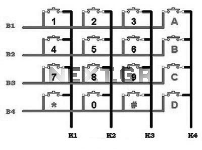
This includes an interface that is simple enough for mastery, as the keypad supports input facilities commonly used in Man-Machine Interface (MMI) applications. For example, various types of keypads can be found in the market. This discussion will focus...

This circuit features high stability and precision, providing a direct current source that can be preset for various electronic devices. The numerical control direct current source designed here effectively reduces output errors caused by component wear, temperature drift, and...
This project shows you how to build a relay controller using the Basic Stamp I interfaced to the PC serial port. The Visual Basic 5 software developed for the interface lets you interact with the Basic Stamp to turn...
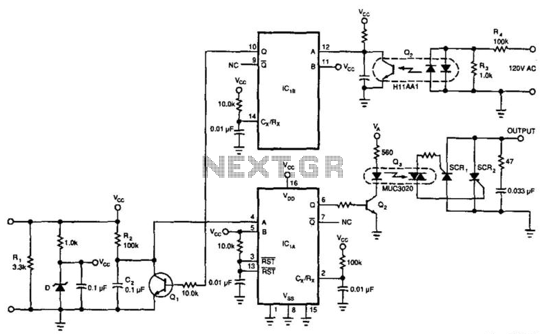
This circuit enables a 4-to-20 mA current loop to control an isolated SCR drive. IC1A and IC1B function as one-shot timers. Q2 detects zero crossings of the 120 Vac line, which triggers one-shot IC1B. IC1A causes Q1 to discharge...
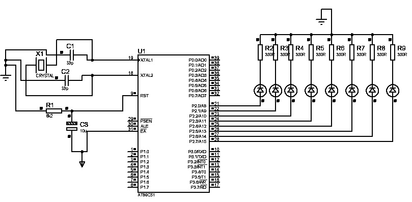
The first "Hello World!" project preferred for microcontrollers is LED blinking. An ATMEL 89C51 (40-pins DIP) microcontroller, based on the 8051 architecture, is used, which is ideal for first-time learning of MCU chips. The program is very simple and...
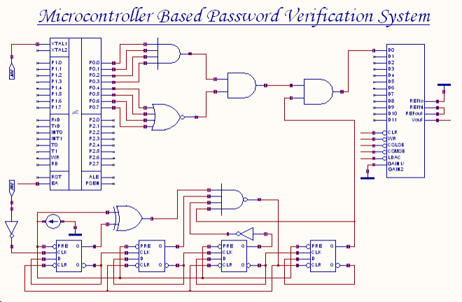
An 8-bit password serves as the input to this system. The password entered by the user is compared with the actual password, which is set in the microcontroller through a microprogram. The outcome of this comparison process generates an...