
Control System for Cold Atom Experiments
Bus buffer, strobe generator and NI6533 adapter board (schematics, layout V3.3 schematics, layout V1, Gerber file), this board is part A above. Courtesy of Gerhard Hendl. Bus System Manual and layout (pdf): Description of the hardware of the parallel bus system. Contains schematic and layout for strobe pulse generator board. Analog Output Design Manual (pdf), Layout (Schematics Layout V2) (pcb123 file V1): 16-bit Digital-to-Analog (DAC) converter design to be used with the parallel bus system. Eight analog channels per board, each has a 1/4 Amp line driver and -10 to +10 Volt range. Digital Output Design Manual (pdf), Layout (Schematics, Layout V3) (pcb123 file, V1): 16 buffered line driver digital outputs per board. RF Synthesizer Manual (new Version 2.x) (pdf), Layout (pcb123 file, gerber files, partlist): Direct Digital Synthesizer (DDS) for radio frequency (RF) from DC to 135MHz. One RF output, one 'control' DAC. Based on AD9852 complete DDS IC, compatible with bus system, rack mountable (V2.1). Box drawing in emachineshop format (V2.0): (center), (lid), (bracket). Bus system testboard (pdf): provides a system bus which can be manually controlled using switches. Very useful for debugging. Cheap 8 channel analog input board (pdf): a cheap board providing eight analog inputs. Useful for testing the analog output boards. Serial port multiplexer(pdf): multiplexes one RS232 serial port on eight RS232 ports. Using this multiplexer one can connect up to eight serial port devices to one PC serial port. Three digital lines select which serial port is used. RF amplifier PCB (Schematics, Layout V2 (pdf)) (Protel&Gerber (zip) V1 schematics (pdf)): a rack mountable RF amplifier (2 Watt at 100MHz, 0.5W at 1GHz) with externally or internally controlled 50dB attenuator and filtered power supply section. Ideal as power stage after a DDS to drive acousto optical modulators. Designed with Protel. Partlist, source and gerber files provided. RF amplifier housing (zip): ProEngineer drawings of housing parts. Layout Software: pcb123 Free software from the board maker, the above layouts have to be used with PCB123 Version 1.1.4.0 -- there are newer versions now, which are not compatible with our files. To place orders with PCB123, you just download the layout software (Version 1.1.4.0), load the layout file and place the order from the software through the internet. Generally, when making single boards, we have etched them ourselves with the various PCB supplies from circuitspecialists.com. This we did for the converter board from the NI card, the transceiver and strobe bit generator board, etc. We never actually ordered DDS boxes from emachineshop.com, but this looks like an interesting option for those without a professional machine shop on location. You can download their free cad software, the files for the DDS box are above. The more modern versions of our electronics in Innsbruck were produced by Katronik. They even purchased and soldered the components onto the PCBs for us.
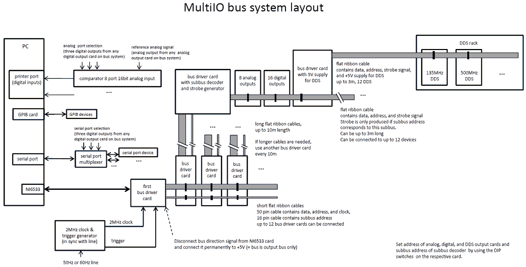
The experiment control system described is a versatile setup designed for precision control in cold atom experiments, particularly for Bose-Einstein condensation studies. The hardware design includes a robust architecture featuring 16-bit Digital-to-Analog Converters (DACs) and digital outputs, which are integral for generating precise analog signals and controlling various experimental parameters. The Direct Digital Synthesizer (DDS) component, based on the AD9852 IC, allows for high-frequency signal generation up to 135 MHz, making it suitable for RF applications in laboratory settings.
The system utilizes a general-purpose parallel bus for communication and control, facilitating easy integration with other devices such as analog inputs and microprocessors. This bus architecture is complemented by additional components like a bus buffer and a strobe generator, which manage signal timing and integrity across the system.
Output connections are standardized with BNC-type connectors, ensuring compatibility with typical laboratory equipment and simplifying the process of connecting to external devices. The power output capabilities, such as the 1/4 Amp line driver and -10 to +10 Volt range for the analog outputs, enhance the system's usability in various experimental setups.
For software integration, the system includes comprehensive control software that interfaces with the hardware, allowing users to program and automate experiments efficiently. The included manuals and schematics provide detailed guidance for assembly and operation, ensuring that users can construct and utilize the system without extensive prior experience in electronics.
Additionally, various auxiliary boards, such as the serial port multiplexer and the RF amplifier, expand the system's functionality, enabling users to connect multiple devices and amplify signals as needed. The design emphasizes cost-effectiveness and accessibility, making it an ideal choice for research groups looking to conduct sophisticated experiments without the burden of high costs associated with commercial systems.We have developed a powerful yet inexpensive and easy to construct experiment control system. The construction of the system together with the control software is described here. All circuits and software are free to download and use for nonprofit. The system was developed for the BEC (Bose-Einstein condensation) experiments in the group of Prof. Mark Raizen at the University of Texas at Austin and is based on a system that one of the authors developed previously for experiments in the group of Christophe Salomon in Paris. It is now used by several other groups, among them the groups of Prof. Jook Walraven, Prof. Rudi Grimm, Prof. Randy Hulet, Prof. Kirk Madison, Prof. Lev Khaykovich and Prof. Gerard Meijer. The visualization software is even used by more groups. The hardware here includes a design for analog outputs (16-bit DACs), digital outputs and a direct digital synthesis device (DDS) on a general purpose parallel bus which is easy to expand upon and interface with a variety of devices (i.e. analog inputs, microprocessors, etc). The hardware outputs are laboratory friendly with BNC-type outputs and line drive capacity. The software is intended for cold atom experiments and contains the code to talk with the hardware developed here.
This system represents a simple to understand and cost effective method to control laboratory experiments. Hardware Manuals and layouts: Bus buffer, strobe generator and NI6533 adapter board (schematics, layout V3.3 schematics, layout V1,Gerber file), this board is part A above.
Courtesy of Gerhard Hendl. Bus System Manual and layout (pdf): Description of the hardware of the parallel bus system. Contains schematic and layout for strobe pulse generator board. Analog Output Design Manual (pdf), Layout (Schematics Layout V2) (pcb123 file V1): 16-bit Digital-to-Analog (DAC) converter design to be used with the parallel bus system. Eight analog channels per board, each has a 1/4 Amp line driver and -10 to +10 Volt range. Digital Output Design Manual (pdf), Layout (Schematics, Layout V3) (pcb123 file, V1): 16 buffered line driver digital outputs per board.
RF Synthesizer Manual (new Version 2.x) (pdf), Layout (pcb123 file, gerber files, partlist): Direct Digital Sythethesizer (DDS) for radio frequency (RF) from DC to 135MHz. One RF output, one `control' DAC. Based on AD9852 complete DDS IC, compatible with bus system, rack mountable (V2.1). Box drawing in emachineshop format (V2.0): (center), (lid), (bracket). Bus system testboard (pdf): provides a system bus which can be manually controlled using switches. Very useful for debugging. Cheap 8 channel analog input board (pdf): a cheap board providing eight analog inputs. Useful for testing the analog output boards. Serial port multiplexer(pdf): multiplexes one RS232 serial port on eight RS232 ports. Using this multiplexer one can connect up to eight serial port devices to one PC serial port. Three digital lines select which serial port is used. RF amplifier PCB (Schematics, Layout V2 (pdf)) (Protel&Gerber (zip) V1 schematics (pdf)): a rack mountable RF amplifier (2 Watt at 100MHz, 0.5W at 1GHz) with externaly or internaly controlled 50dB attenuator and filtered power supply section.
Ideal as power stage after a DDS to drive acousto optical modulators. Designed with Protel. Partlist, source and gerber files provided. RF amplifier housing (zip): ProEngineer drawings of housing parts. Layout Software: pcb123 Free software from the board maker, the above layouts have to be used with PCB123 Version 1.1.4.0 -- there are newer versions now, which are not compatible with our files. To place orders with PCB123, you just download the layout software (Version 1.1.4.0), load the layout file and place the order from the software through the internet.
Generally, when making single boards, we have etched them ourselves with the various PCB supplies from circuitspecialists.com. This we did for the converter board from the NI card, the transceiver and strobe bit generator board, etc.
We never actually ordered DDS boxes from emachineshop.com, but this looks like an interesting option for those without a professional machine shop on location. You can download their free cad software, the files for the DDS box are above. The more modern versions of our electronics in Innsbruck were produced by Katronik. They even purchased and soldered the components onto the PCBs for us. 🔗 External reference
Related Circuits
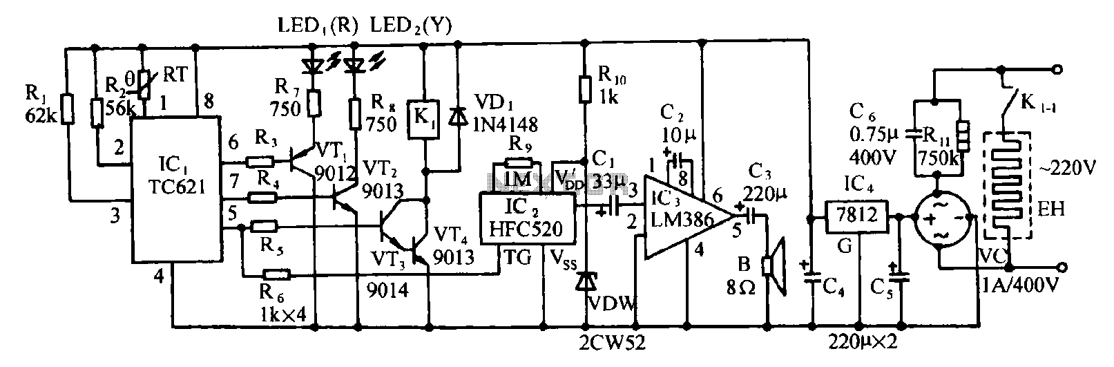
Eggs hatch chicks at temperature requirements within the range of 36 to 39 degrees Celsius. The temperature sensor integrated circuits utilize the TC621 temperature control circuit, which has fewer external components, is low cost, and offers high reliability. Users...
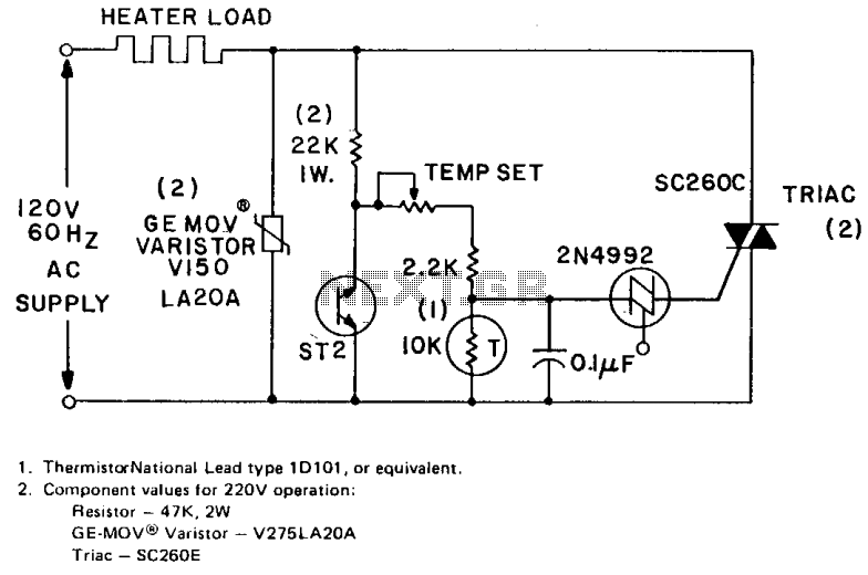
The circuit can control up to 6 kW of heating with moderate gain using a 25-amp triac (SC260D). Feedback is provided by a negative temperature coefficient (NTC) thermistor, which is positioned near the environment being temperature controlled. The temperature...
Closed loop motor control is utilized for maintaining constant speed in motor operations. This means that the motor's speed is regulated to remain steady. Closed loop motor control systems, commonly referred to as servo control systems, are essential in applications...
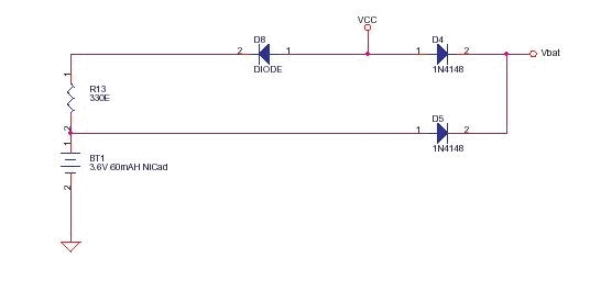
This circuit functions as a low-cost battery backup solution for SRAM and microcontroller/microprocessor applications. It utilizes 1N4148 diodes to prevent battery discharge back to the power source. Diode D8 provides a one-way path for charging the battery through resistor...
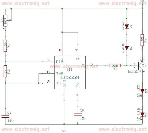
This Remote control Jammer device is useful when blocking someone from using the remote control (such as children who frequently change the channels on the TV). This remote control jammer is very simple and uses two infrared LEDs that...
A compact thermal control solution for Dense Wavelength Division Multiplexing (DWDM) laser modules can be implemented using a MAX8520/21 and a single operational amplifier. The proposed thermal control solution utilizes the MAX8520 or MAX8521, which are highly efficient, low-dropout linear...
Warning: include(partials/cookie-banner.php): Failed to open stream: Permission denied in /var/www/html/nextgr/view-circuit.php on line 713
Warning: include(): Failed opening 'partials/cookie-banner.php' for inclusion (include_path='.:/usr/share/php') in /var/www/html/nextgr/view-circuit.php on line 713