
Heater temperature controller

The described circuit operates as a temperature-controlled heating system capable of managing significant power levels, specifically up to 6 kW. It employs a triac (SC260D), which is a semiconductor device that can control AC power. The triac's operation is modulated by feedback from an NTC thermistor, which is sensitive to temperature changes. The placement of the thermistor is critical as it must be located close to the heating element to accurately sense the temperature of the environment.
The temperature set potentiometer allows for user adjustment of the desired temperature level. This potentiometer sets a reference point for the system's operation. As the temperature in the environment rises, the resistance of the thermistor decreases. This change in resistance alters the conduction angle of the triac, effectively reducing the power supplied to the heating element. This feedback mechanism ensures that the temperature remains within the desired range, preventing overheating and promoting energy efficiency.
The inclusion of the ST2 diac in the circuit serves a dual purpose. It acts as a back-to-back Zener diode, providing a protective function against voltage spikes and ensuring stable operation. The diac's negative resistance characteristic plays a crucial role in stabilizing the line voltage. When the input line voltage rises, the diac responds by triggering earlier in the AC cycle, which reduces the average charging voltage applied to the 0.1 µF capacitor. This interaction helps maintain consistent performance of the heating control circuit, even in the presence of fluctuations in the supply voltage.
Overall, this circuit exemplifies a robust design for temperature regulation in high-power heating applications, integrating essential components to achieve efficient and reliable operation.The circuit can control up to 6 kW of heating, with moderate gain, using a 25-amp triac (SC260D). Feedback is provided by the negative temperature co-efficient (NTC) thermistor, which is mounted adjacent to the environment being temperature controlled. The temperature set potentiometer is initially adjusted to the desired heating level. As the thermistor becomes heated by the load, its resistance drops, phasing back the conduction angle of the triac, so the load voltage is reduced.
The ST2 diac is used as a back-to-back zener diode. Its negative resistance region in its E-I characteristic provides a degree of line voltage stabilization. As the input line voltage increases, the diac triggers earlier in the cycle and, hence, the average charging voltage to the 0.1 /iF capacitor, decreases.
Related Circuits
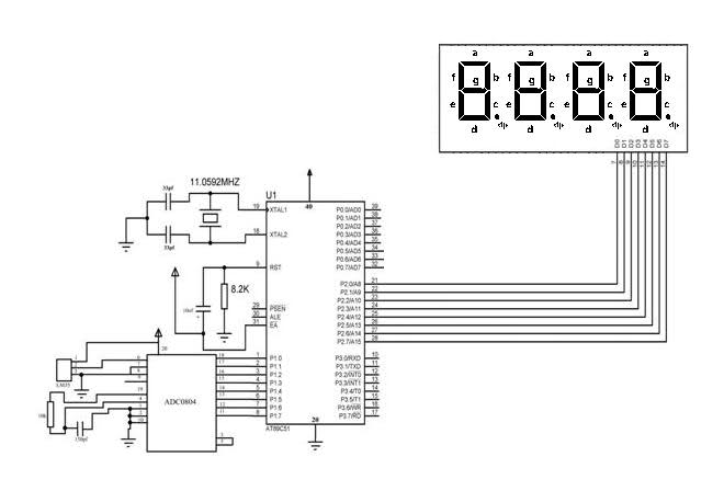
The temperature sensor was connected to 8 LEDs provided with the DeccanRobots package, successfully displaying the temperature in binary format. However, when attempting to use a microcontroller with a program designed to output the temperature on 4 seven-segment displays...
This kit is designed to control the speed of AC motors with carbon brushes, applicable to devices such as drills, saws, and vacuum cleaners. Unlike standard dimmers, this kit performs a phase cut only once per period. The timing...
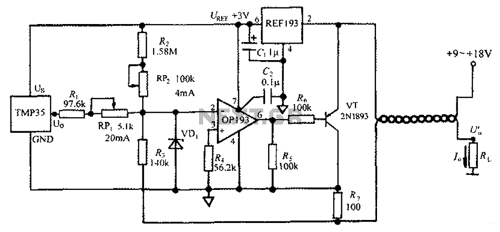
The circuit consists of a TMP35 temperature transmitter that converts a voltage signal output from the TMP35 into a standard 4 to 20 mA current signal. This configuration is suitable for use in automated instrumentation and industrial temperature control...
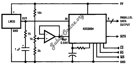
This is a design for a temperature-to-digital converter circuit that is controlled by the LM35 integrated circuit. The LM35 is a precision integrated circuit temperature sensor, whose output voltage is linearly proportional to the Celsius temperature. The circuit utilizes the...
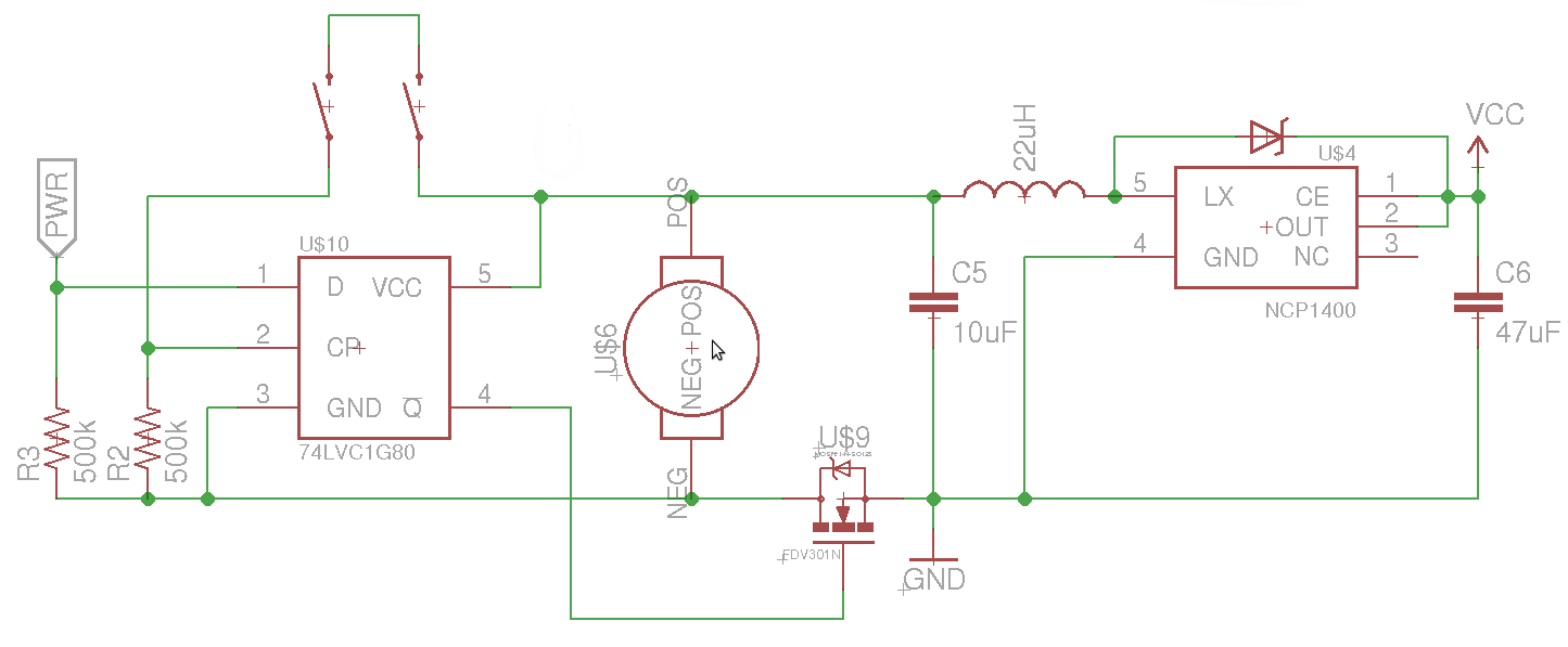
The objective is to control the power to a load, specifically an 8051-based microcontroller (uC), using two switches. When the uC is powered on, it sets the PWR pin high. Upon pressing the switches again, pin 4 of the...
A pulse width modulator (PWM) is a device that may be used as an efficient light dimmer or DC motor speed controller. The circuit described here is for a general purpose device that can control DC devices which draw...