
Closed Loop PWM Motor Control
Closed loop motor control systems, commonly referred to as servo control systems, are essential in applications requiring precise speed and position management. In such systems, feedback mechanisms are implemented to continuously monitor the output of the motor. This feedback is typically obtained from sensors that measure various parameters such as speed, position, and torque.
In a typical closed loop motor control circuit, a microcontroller or digital signal processor (DSP) serves as the central processing unit. It receives input from the sensors and compares the actual motor speed with the desired speed setpoint. If discrepancies are detected, the controller adjusts the input signal to the motor driver, which modulates the power supplied to the motor, thus correcting the speed.
The key components of a closed loop motor control circuit include:
1. **Motor**: The primary actuator that converts electrical energy into mechanical motion.
2. **Sensors**: Devices such as encoders or tachometers that provide real-time feedback on the motor's speed and position.
3. **Controller**: A microcontroller or DSP that processes the feedback data and generates control signals.
4. **Motor Driver**: An interface that amplifies the control signals from the controller to drive the motor effectively.
5. **Power Supply**: Provides the necessary voltage and current to the motor and driver circuit.
The advantages of closed loop control systems include improved accuracy, better performance under varying load conditions, and enhanced stability. By continuously adjusting the motor's operation based on real-time feedback, these systems can effectively reduce overshoot and oscillations, ensuring a smooth and consistent performance in various applications such as robotics, CNC machinery, and automated conveyor systems.Closed Loop Motor Control Closed loop (servo) control is used to make a constant speed motor control. Constant speed means that the speed of the motor will be. 🔗 External reference
Related Circuits

The main oscillator is printed in blue and is voltage controlled. In this construction, the VCO range is 88 to 108 MHz. As you can see from the blue arrows, some energy goes to an amplifier and some energy...
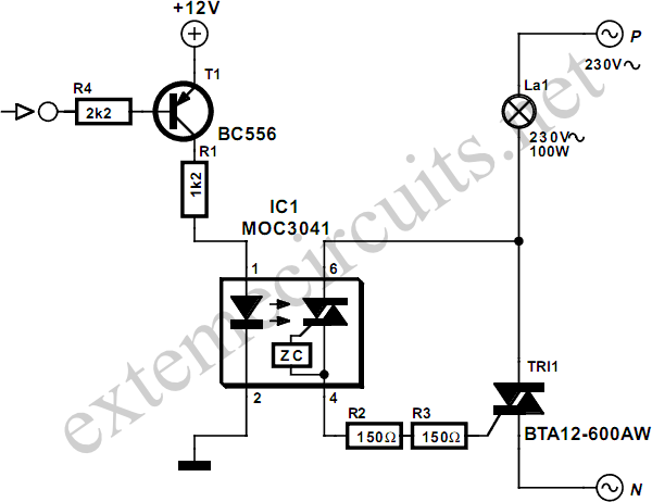
When switching a mains voltage, a relay serves as a straightforward solution for applications involving long switching times and high currents. However, for lower currents and applications requiring rapid switching, such as sound-to-light systems, a relay may not be...
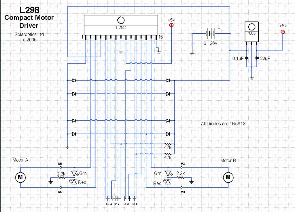
This circuit is beneficial for connecting a computer to homemade robotics. It is straightforward to construct and operate, capable of controlling two DC motors of varying current and voltage ratings, contingent on the specifications of the relays used. Additionally,...
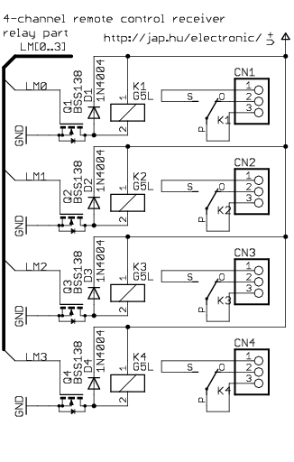
This is a general-purpose remote control project utilizing programmable PIC microcontrollers. Schematics are provided for using infrared (IR) or radio frequency (RF) media. If microcontroller programming is unfamiliar, fixed encoder and decoder integrated circuits can be employed instead. Well-known...
The ArduinoISP Bootloader/Programmer Combination Shield (not displayed) works with an Arduino equipped with a USB to serial chip (e.g., Arduino Uno) to upload the bootloader and sketches to a DIYduino. A USB to Serial programmer can also be utilized...
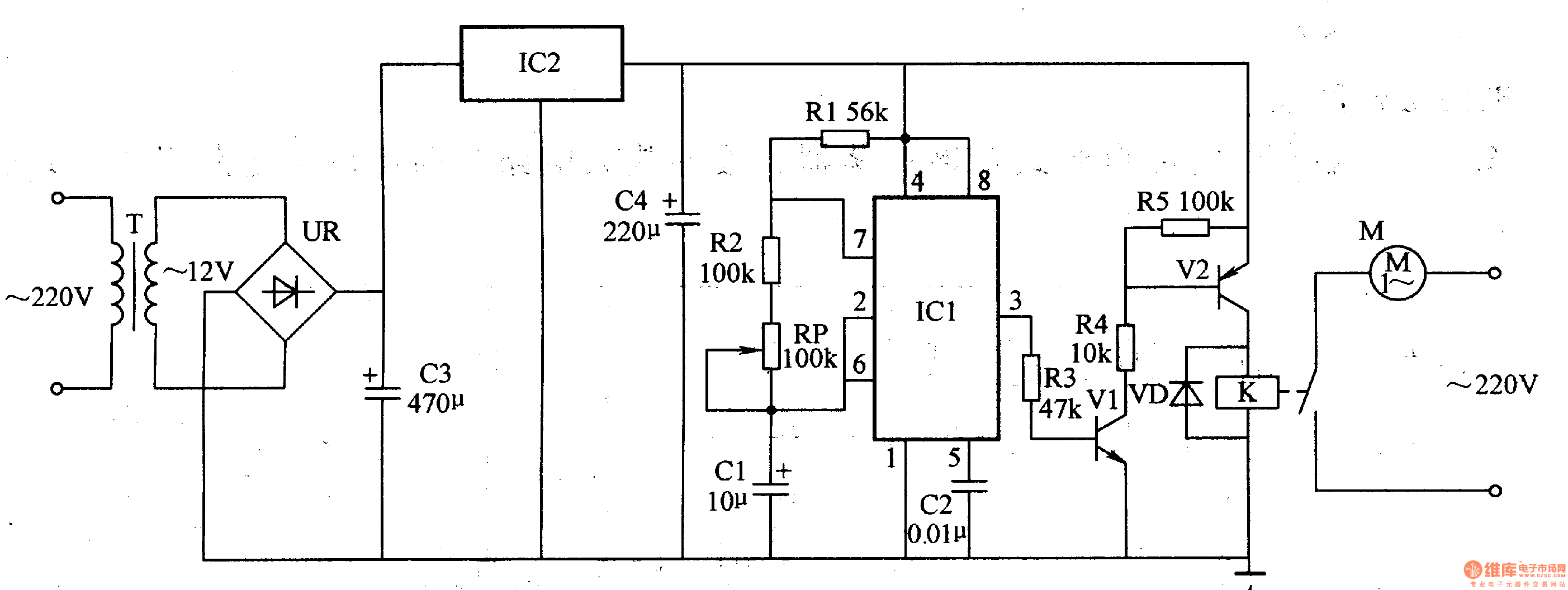
The medical ventilator controller circuit consists of an astable oscillator, a control circuit, and a power supply circuit. The astable oscillator is constructed using resistors R1, R2, a potentiometer RP, capacitors C1, C2, and a time base integrated circuit...