
Controlled pulse signal generating circuit
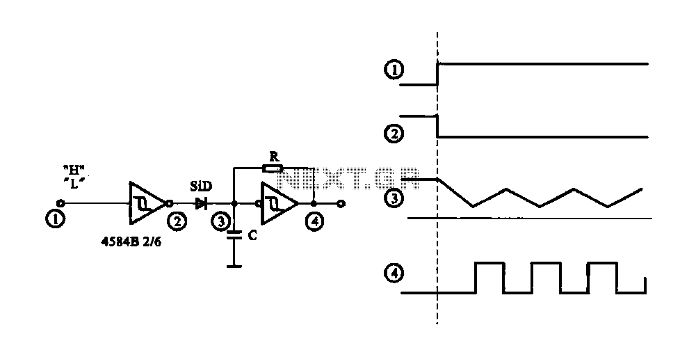
This pulse signal generating circuit operates based on a simple yet effective design that utilizes a combination of digital logic components, such as flip-flops, resistors, and capacitors. The circuit's primary function is to produce a square wave output signal that can be controlled through an input signal.
When the input terminal O receives a high signal, it triggers a flip-flop, which changes its state and allows current to flow through the output stage. This transition generates a pulse output, which can be used for various applications, such as timing circuits, frequency modulation, or as a clock signal for other digital circuits. The duration and frequency of the output pulse can be adjusted by modifying the values of the resistors and capacitors in the timing circuit.
Upon receiving a low signal at the input terminal O, the flip-flop resets to its initial state, cutting off the current flow and halting the output pulse. This feature allows for precise control over the timing of the output signal, making it suitable for applications that require on-demand pulse generation.
The design can be further enhanced by incorporating additional components such as diodes for signal conditioning or transistors for driving higher loads, depending on the requirements of the specific application. Additionally, integrating a microcontroller can provide programmable control over the pulse width and frequency, expanding the circuit's functionality and adaptability in various electronic systems.Controlled pulse signal generating circuit FIG controllable pulse signal generating circuit, when the input terminal O start (start) pulse signal (input high), electric road be gan work output pulse signal; when O stop signal input terminal (low level), the circuit stop working, no pulse signal output.
Related Circuits
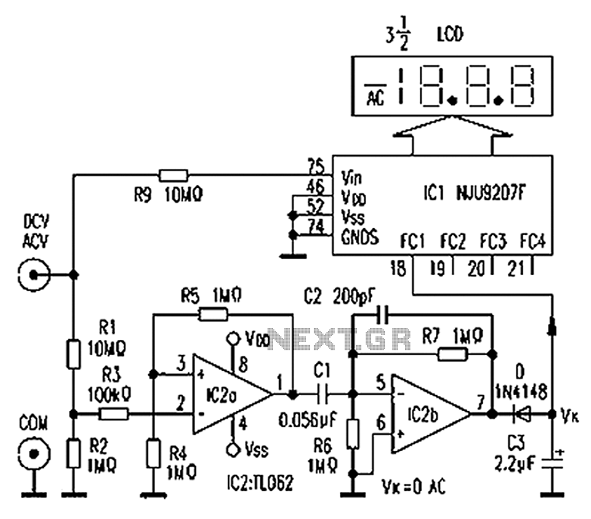
The circuit depicted in the figure illustrates an automatic AC/DC converter for a digital multimeter. Typically, standard digital multimeters require manual intervention to switch between AC and DC measurements. The new DT860D digital multimeter utilizes the NJU9207F automatic range...
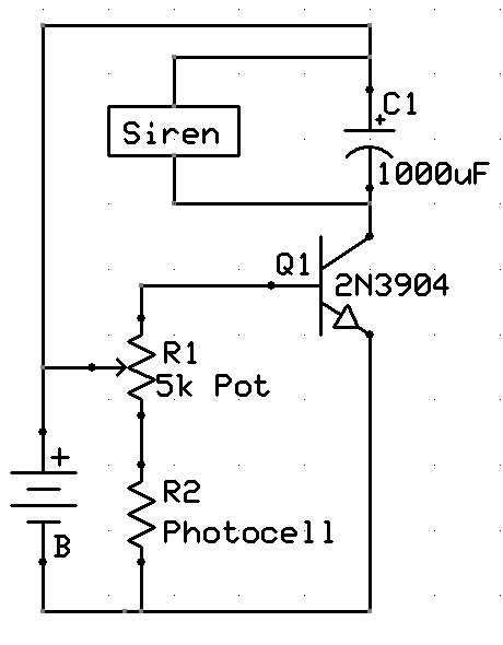
A new user has recently discovered a Laser Alarm System and has decided to explore this project. The Laser Alarm System is a security device that utilizes laser beams to detect unauthorized entry or movement within a designated area. The...
A versatile circuit of an IF signal generator that may be of interest to radio hobbyists and professionals alike. Transistors T1 and T2 form an astable multivibrator oscillating in the audio frequency range of 1 to 2 kHz. An...
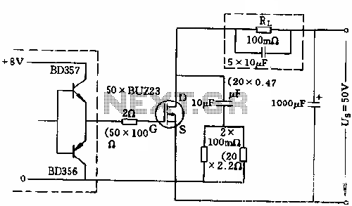
The circuit employs 50 BUZ23 field effect transistors (FETs) arranged in parallel, with a tube blocking voltage of 100V. The control power required is minimal, eliminating the risks associated with second breakdown and the positive temperature coefficient phenomenon in...
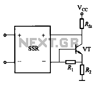
A DC solid-state relay (DC-SSR) driving a high-power load circuit is illustrated in (a) below; the high-power load driving circuit is depicted in (b) below. The DC solid-state relay (DC-SSR) serves as a crucial component in controlling high-power loads, providing...
The only drawback of a single operational amplifier (op-amp) stage is that it inverts the signal, necessitating an additional inverting buffer to restore the original phase if absolute phase is a concern. Various schematics exist for both configurations, but...