
Simple IF Signal Generator

The described IF signal generator circuit is designed to provide flexibility and adaptability for various radio applications. The astable multivibrator configuration formed by transistors T1 and T2 serves as a reliable source of audio frequency oscillation, operating within the range of 1 to 2 kHz. This multivibrator generates a square wave output, which is essential for modulating the RF signal produced by transistor T3.
Transistor T3 functions as the core RF oscillator, which is essential for generating the intermediate frequency signal. The incorporation of a 455 kHz ceramic filter ensures that the output signal remains stable, which is crucial for maintaining signal integrity in radio applications. The coupling of the AF signal from the collector of T2 to the emitter of T3 through capacitor C3 allows for effective modulation of the RF signal.
The tank circuit, which is pivotal in determining the oscillation frequency of T3, consists of a medium wave oscillator coil, a fixed capacitor (C5), and a portion of a gang capacitor (C6). This arrangement allows for precise tuning and adjustment of the oscillator frequency, facilitating the generation of different intermediate frequencies as required. The ability to modify the circuit for other frequencies by replacing the ceramic filter or resonator, as well as adjusting the tank circuit components, enhances the versatility of the design.
Additionally, the circuit includes resistors R6 and R7, which provide a means for bias adjustment. This feature is particularly useful for fine-tuning the performance of the transistors, ensuring optimal operation within the desired frequency range. Overall, this IF signal generator circuit presents a valuable tool for both amateur and professional radio enthusiasts, offering a robust platform for experimentation and development in RF applications.A versatile circuit of IF signal generator which may be of interest to radio hobbyists and professionals alike. Transistors T1 and T2 form an astable multivibrator oscillating in the audio frequency range of 1 to 2 kHz.
RF oscillator is built around transistor T3. Here again a 455kHz ceramic filter/resonator is employed for obtaining stable IF. The AF from multivibrator is coupled from collector of transistor T2 to emitter of transistor T3 through capacitor C3. The tank circuit at collector of transistor T3 is formed using medium wave oscillator coil of transistor radio, a fixed 100pF capacitor C5 and half section of a gang capacitor (C6).
The oscillator section may be easily modified for any other intermediate frequency by using ceramic filter or resonator of that frequency and by making appropriate changes in the tank circuit at collector of transistor T3. Slight adjustment of bias can be affected by varying values of resistors R6 and R7, if required. 🔗 External reference
Related Circuits
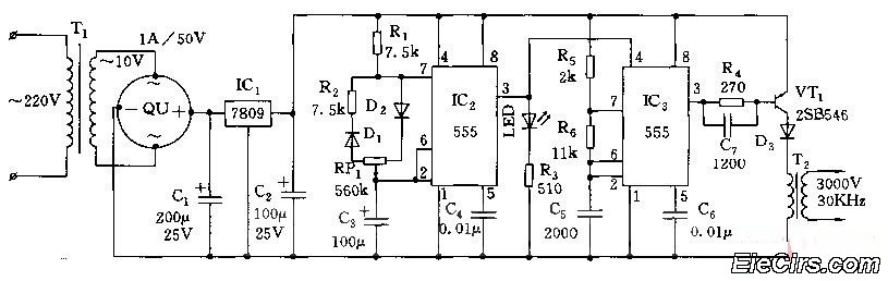
Adjust the RP1 to modify the pulse duty cycle of IC2, which in turn alters the pulse oscillation time of IC3. This regulation allows for the control of ozone generation time, effectively changing the concentration of ozone in the...
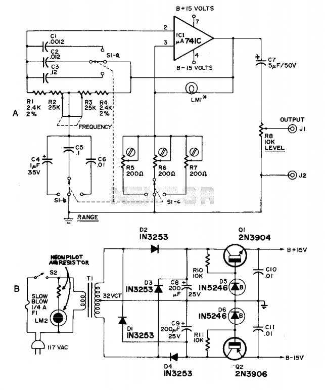
This high-quality, low-cost generator operates within a frequency range of 20 Hz to 20 kHz across three bands, maintaining less than 1% distortion. It utilizes LM1-10 V at 14 mA (344,1869, 914) or 10 V at 10 mA (913,...
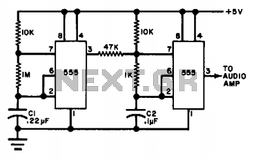
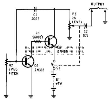
The circuit utilizes either two 555 timers or a single dual timer. Capacitor C1 regulates the speed of the warble effect, while capacitor C2 defines the pitch. The specified values are expected to generate a notably distinctive signal. The described...
This circuit generates a good 1KHz sinewave adopting the inverted Wien bridge configuration (C1-R3 & C2-R4). It features a variable output, low distortion and low output impedance in order to obtain good overload capability. A small filament bulb ensures...
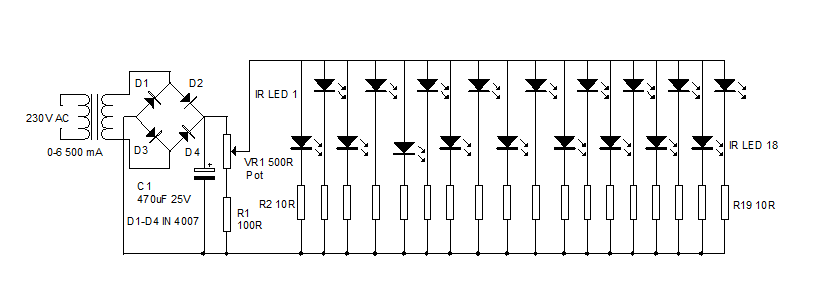
An infrared illuminator emits light in the infrared spectrum and is widely used in night vision cameras to capture images in the dark, particularly in applications such as CCTV cameras. Infrared illuminators are essential components in various surveillance and imaging...
Useful for troubleshooting audio, video, and lower frequency RF amplifiers. This circuit generates a signal that is rich in harmonics. The circuit designed for troubleshooting audio, video, and lower frequency RF amplifiers is crucial for diagnosing issues in these systems....