
Conversation Recorder

The circuit operates by detecting the state of the telephone handset. When the handset is lifted, a change in voltage occurs across the telephone line, which is utilized to trigger the operation of the tape recorder. Resistors R1 and R2 form a voltage divider network, which reduces the voltage from the telephone line to a safe level suitable for the MIC-IN input of the tape recorder. The specific values chosen for R1 and R2 are crucial, as they must match the input impedance of the tape recorder's MIC-IN socket to ensure optimal signal transfer without distortion.
Capacitor C1 serves an important function by blocking any direct current (DC) component from the telephone line, allowing only the alternating current (AC) audio signals to pass through to the tape recorder. This ensures that the recording is free from unwanted DC offsets that could affect the audio quality.
Relay RL1 plays a pivotal role in the circuit by acting as a switch that controls the power to the tape recorder. When the handset is lifted, the relay is energized, closing the circuit and powering the tape recorder. Conversely, when the handset is placed back, the relay is de-energized, cutting off power to the tape recorder, thus stopping the recording.
The circuit is designed to operate with a standard telephone line voltage of 48 volts in the on-hook condition, which is typical for many residential telephone systems. The design can be adapted for different tape recorder models by adjusting the resistor values and ensuring compatibility with the specific input requirements of the MIC-IN socket. This automatic switching mechanism enhances convenience by allowing users to record audio without manual intervention, thus streamlining the recording process.This circuit enables automatic switching-on of the tape recorder when the handset is lifted. The tape recorder gets switched off when the handset is replaced. The signals are suitably attenuated to a level at which they can be recorded using the MIC-IN socket of the tape recorder. Resistors R1 and R2 act as a voltage divider. The voltage appearing across R2 is fed to the MIC-IN socket of the tape recorder. The values of R1 and R2 may be changed depending on the input impedance of the tape recorders MIC-IN terminals.
Capacitor C1 is used for blocking the flow of DC. The second part of the circuit controls relay RL1, which is used to switch on/off the tape recorder. A voltage of 48 volts appears across the telephone lines in on-hook condition. 🔗 External reference
Related Circuits
The 2 pushbuttons = S1: Start/Pause. S2: Stop/Reset. If you want to play your message, put S3 at Play. Then push S1 to start playing and again to pause. If you want to delete your message press S2 twice....
Automated frog call data loggers have been effectively utilized to gather information on: (1) species presence during sampling, enabling the reliable recording of species that may be overlooked due to time constraints; (2) life history and phenology details, such...
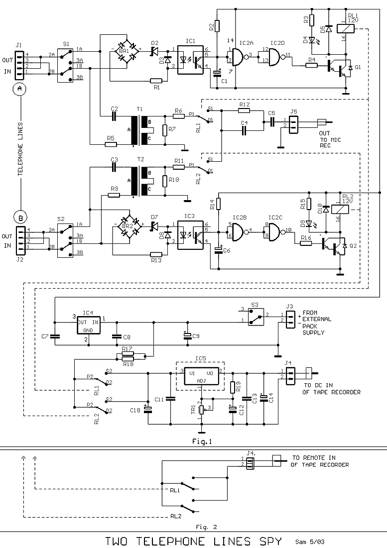
Many times exists the need recording some conversations from a telephone line and this it's relatively easy. If we want however to have the possibility recording from two telephone lines simultaneously in a tape recorder, we needed a circuit...
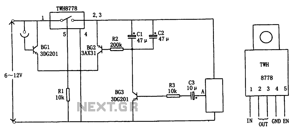
The circuit illustrated in FIG X pertains to automatic circuitry for US recorders. It primarily utilizes a new power switching device, TWH8778, which simplifies the design and eliminates the need for extensive debugging. The TWH8778's configuration and pin functions...

Basic features include an internal 512k-bit EEPROM, allowing for continuous recording and playback at any time, with long-term retention of voice data after power loss. The voice recording time is 20 seconds, and it supports segmented recording and playback....
This circuit will allow you to connect any tape recorder that has a mic and remote input to a phone line and automatically record both sides of a conversation whenever the phone is in use. You will need to...