
Use SR9F26C ordinary language learning machine tape recorder and circuit diagram

The SR9F26C is a versatile audio recording and playback chip designed for applications requiring reliable long-term data retention. The internal 512k-bit EEPROM provides ample storage for audio data, enabling users to record up to 20 seconds of voice. This feature is particularly useful in applications such as voice recorders, alarm systems, and interactive devices where audio feedback is essential.
The segmented recording capability allows for the storage of multiple audio snippets, which can be played back in sequence or individually, enhancing the chip's utility in complex audio applications. The playback function is designed to be straightforward, ensuring that audio can be accessed and played back with minimal delay.
The physical dimensions of the chip, housed in a 28-foot flat package measuring 1mm by 16mm, make it suitable for compact electronic designs where space is at a premium. The pinout diagram provides detailed information on the connections required for integration into a circuit, facilitating ease of use for engineers and designers.
Overall, the SR9F26C is an efficient solution for embedded systems requiring audio functionality, combining compact size with robust performance features for seamless integration into various electronic projects. Basic features: O internal containing 512k bit EEPROM, you can always recording, playback at any time, long-term retention after power voice. Voice recording time is 20s. can b e segmented recording, playback. 28 feet flat package, the chip area is 1mm 16rnm. SR9F26C pinout diagram.
Related Circuits
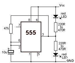
This LED flasher circuit utilizes the 555 timer integrated circuit (IC). The circuit diagram is straightforward and requires only a few external components. When operational, the red LEDs will flash sequentially at a predetermined frequency, similar to the indicators...
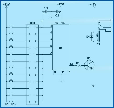
Circuit diagram schematics of electronic keys, electronic locks, digital electronic locks, transistor code locks, and combination electronic locks. The circuit schematics for electronic locking mechanisms encompass a variety of designs tailored to enhance security and convenience in access control systems....
Frequency-Shift Keying (FSK) is a type of frequency modulation where the modulating signal alters the output frequency between specific predetermined values. When issues occur during the demodulation of FSK signals, utilizing an FSK filter circuit can be beneficial. Frequency-Shift Keying...
The voltage to be sampled is applied to the input of R2, a 100K linear taper potentiometer, while the other end of R2 is grounded. Consequently, the signal level that is sent to the buffering level shifter U1-A and...
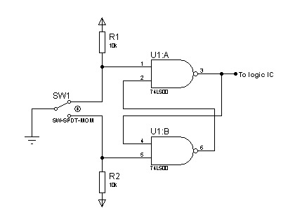
In most digital electronics projects that utilize various types of switches, switch bounces are frequently encountered. These are additional glitches that occur following the actual operation of the switch. These small pulses can disrupt the proper functioning of the...
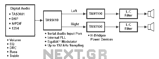
A digital amplifier is a new device that IC manufacturers are eager to capitalize on, leading to the launch of unique digital amplifier products. Below are brief descriptions of some representative devices. The TA2022, produced by Tripath, is an...