
Speech Recorder (ISD2560)
The circuit described incorporates a voice recording and playback system using the ISD2560 IC, which facilitates the recording and playback of audio messages. The system is controlled by two pushbuttons (S1 and S2) and a change-over switch (S3) that allows for different operational modes: Play and Record.
The S1 pushbutton serves dual functions; it initiates playback when in Play mode and pauses playback when pressed again. The S2 pushbutton is used for stopping the playback or resetting the system. To delete a recorded message, S2 must be pressed twice in quick succession, which clears the stored audio data.
The change-over switch (S3) is pivotal in selecting the operational mode of the circuit. When positioned at "Play," the system is set to playback the recorded message, whereas switching to "Rec" allows the user to record a new message. During recording, S1 is pressed to start the recording process, while S2 is utilized to stop it.
The components listed include various resistors (R1 to R10) and capacitors (C1 to C11) that are essential for biasing, filtering, and stabilizing the circuit. The resistors range from 1kΩ to 1MΩ, with specific values assigned to control gain and timing functions. Capacitors, with values up to 100nF, are used for decoupling and timing applications, ensuring stable operation of the ICs.
The power supply for the circuit is managed by the LM78L05 voltage regulator (IC2), which provides a stable 5V output necessary for the operation of the ISD2560 (IC1) and the audio amplifier (LM386, IC3). The output from the LM386 is directed to an 8-ohm speaker, providing audio output for playback.
Microphone input is facilitated by a condenser microphone (MIC), which captures audio during the recording phase. The various capacitors, including E1 to E4, serve as coupling and bypass capacitors, ensuring audio fidelity and power stability throughout the circuit.
Overall, this circuit design offers a compact solution for audio recording and playback, suitable for applications where simple user interaction is required.The 2 pushbuttons = S1: Start/Pause. S2: Stop/Reset. If you want to play your message, put S3 at Play. Then push S1 to start playing and again to pause. If you want to delete your message press S2 twice. If you want to record a message put S3 at Rec. Then push S1 to start and S2 to stop. PARTS LIST R1 = 1k R2 = 470k R3 = 10k R4 = 5k1 R5 = 4k7 R6,7 = 100k R8,9 = 1M R10 = 10R C1-10 = 100nF/63V C11 = 47nF/63V E1,4 = 220uF/16V E2 = 4u7F/16V E3 = 22uF/16V IC1 = ISD2560 + socket IC2 =LM78L05 IC3 = LM386 + socket MIC = Condensator microphone S1,2 = Pushbutton (S1 = Start and Pause. S2 = Stop and Reset) S3 = Change-over switch H?jttaler = 8R speaker 🔗 External reference
Related Circuits
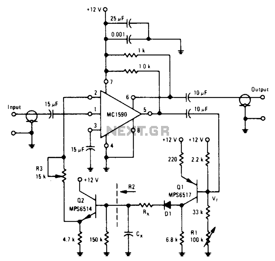
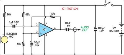
An amplifier designed to achieve a voltage gain of approximately 20, utilizing the MPS6517 PNP transistor in the emitter follower configuration. The RI controller allows for adjustment of the transistor's quiescent point. The output signal is activated only when...
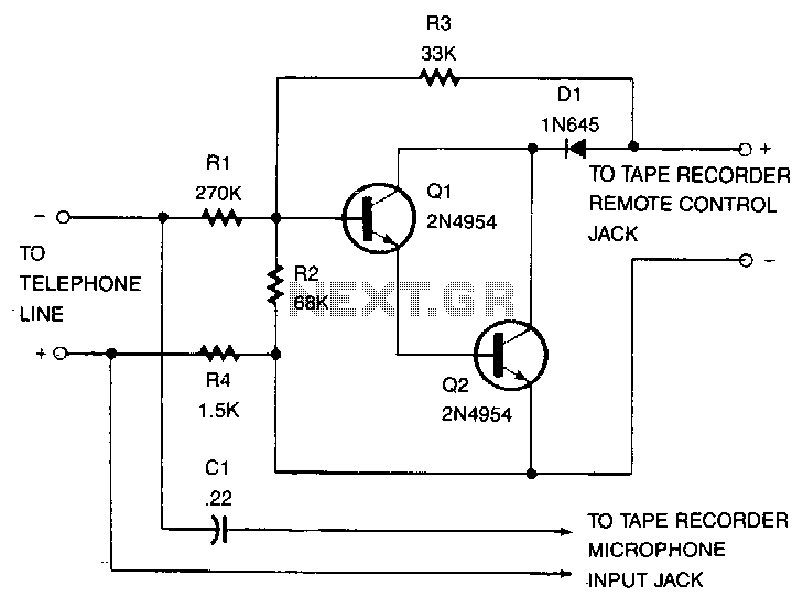
This recorder can be connected to telephone lines almost anywhere, and it does not require an external power source. The switch terminals of the tape recorder are connected to a pair of transistors configured as Darlington pairs, which are...
The objective of this digital electronics project is to record messages using a dedicated voice recorder integrated circuit. Recordings are stored in non-volatile memory cells, ensuring that messages remain saved even when power is removed from the device. The...
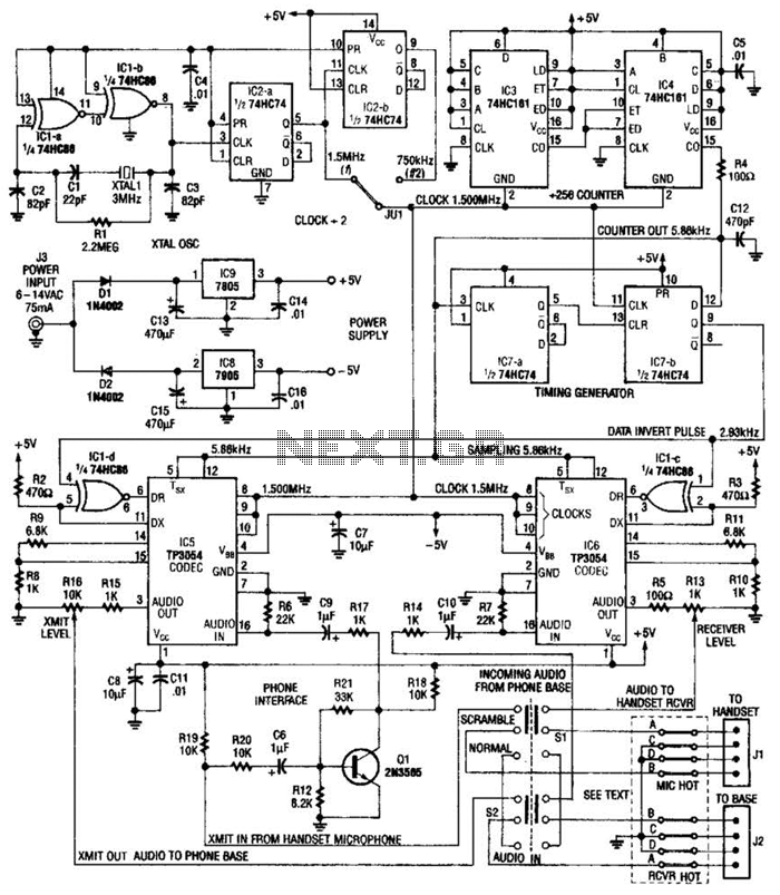
This circuit utilizes digital techniques to implement the frequency-inversion algorithm by digitizing the audio, inverting the sign of every alternate sample, and performing D/A conversion on the resulting data. The outcome is an inverted frequency spectrum. Additionally, the circuit...
A wife was working on a doctoral dissertation that involved fieldwork, specifically personal interviews in various settings. The challenge was to find a suitable technical solution for recording these interviews. Passing a tape recorder or microphone back and forth...
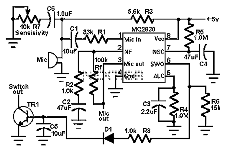
The circuit schematic utilizes the MC2830 voice circuit. Traditional voice circuits are unable to differentiate between speech and noise in the input signal. In noisy environments, such as those caused by switches, this limitation is significant. To address this...