
Courtesy Light Extender

The circuit employs a combination of capacitors, resistors, and transistors to manage the operation of the courtesy light effectively. The 33 µF capacitor plays a critical role in timing the light duration and controlling the fade-out effect. The use of diode D1 prevents backflow of current, ensuring that the discharge path is well-defined when the door is opened. The transistors Q1, Q2, and Q3 are configured in a manner that allows for both the activation and gradual deactivation of the courtesy light, enhancing user experience by providing adequate illumination when entering or exiting the vehicle.
The relay system adds a layer of safety, ensuring that the courtesy light function does not interfere with the car's alarm system. By isolating the circuit from the central locking mechanism, potential issues such as inadvertent activation or failure of the alarm system are mitigated. The 1 MΩ resistor serves to limit the charging current of the capacitor, allowing for a controlled rise in voltage that dictates the timing of the light's fade-out. Overall, this circuit design provides a practical solution for extending courtesy light functionality while maintaining compatibility with existing vehicle security systems.In essence, this circuit is a 15 to 20-second courtesy light extender for cars. It is activated in the usual way by opening a door but it also samples the negative lock/unlock signals from a car alarm or central locking and does two more things. First, when an unlock signal is received, it turns on the courtesy light for 15-20 seconds before you o
pen the door. Second, when a lock signal is received, it turns off the courtesy light immediately, with no fade-out. This is done to eliminate false triggering of the burglar alarm through current drain sensing. When a car door is open or the unlock relay is activated, the 33 µF capacitor discharges through diode D1 and this keeps transistor Q1 turned off.
This allows Q2 and Q3 to turn on and the courtesy lamp is activated. When the door is closed, the courtesy lamps stay illuminated and the 33 µF electrolytic capacitor starts charging through the associated 1MO resistor. As the voltages rises, Q1 turns on slowly, turning off Q2 and Q3 which gradually fades out the courtesy lamp.
If a lock signal from the central locking system is received, relay 1 closes and charges the capacitor instantly, so the lamp turns off immediately. Relays were used to interface to the central locking/alarm system as a safety feature, to provide isolation in case something goes wrong.
🔗 External reference
Related Circuits
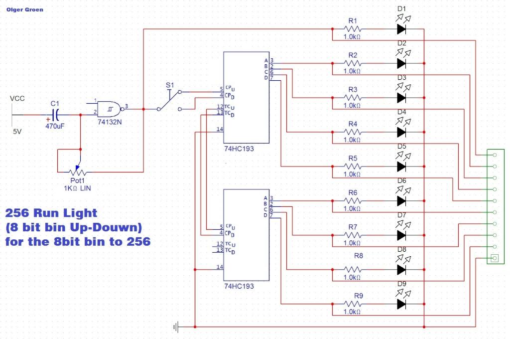
Switch S1 allows for direction change (Up/Down), Pot1 adjusts the clock speed, and LED D1 serves as an indicator for the clock speed. The circuit utilizes a switch (S1) to control the direction of operation, allowing for two modes: upward...
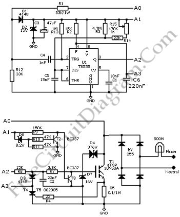
This circuit is a soft light dimmer that utilizes the IGBT STGP10N50A and the TS555 timer as its primary components. The soft light dimmer circuit is designed to control the brightness of incandescent lamps or other resistive loads by...
A relatively simple circuit for controlling a stair walkway light with a delay feature. The circuit has a drawback in that the voice activation is somewhat less sensitive, making it sometimes difficult to trigger with general conversation. However, it...
The described circuit counts the number of interruptions of an infrared beam. This could be used to tally the number of people entering a room or to monitor how often an object, such as a ball, passes through an...

This simple circuit drives six LEDs in a "Knightrider scanner mode." Power consumption primarily depends on the type of LEDs used, particularly when utilizing a 7555 (the CMOS version of the 555 timer). The circuit is designed to create a...
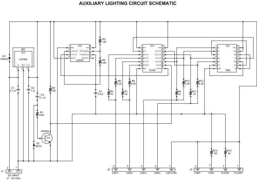
This article outlines a lighting circuit designed to create a glowing firebox effect while providing constant illumination for classification lamps and an interior cab light. It includes comprehensive information necessary for constructing the circuit, such as a detailed schematic,...