
Knightrider lights for model cars circuit

The circuit is designed to create a visual effect reminiscent of the iconic "Knightrider" vehicle, where the LEDs light up sequentially in a left-to-right and right-to-left pattern. The heart of the circuit is the 7555 timer IC, which operates in astable mode to generate a pulse-width modulation signal. This signal is then used to control the timing of the LED illumination.
In this configuration, six LEDs are connected to output pins of the 7555 timer through current-limiting resistors to prevent excessive current flow that could damage the LEDs. The resistors are calculated based on the forward voltage and current specifications of the chosen LEDs. For instance, if using standard 20mA LEDs with a forward voltage of 2V, a resistor value can be determined using Ohm's law to ensure proper operation.
The timing of the LED sequence is adjustable by varying the resistor and capacitor values connected to the 7555 timer. By changing these components, the delay between LED activations can be modified, allowing for customization of the scanning speed.
Additionally, the circuit may incorporate a decade counter or shift register to facilitate the sequential lighting of the LEDs, ensuring that only one LED is illuminated at a time. This arrangement not only enhances the visual effect but also reduces overall power consumption, as fewer LEDs are lit simultaneously.
Power supply requirements for this circuit can vary, but typically a 9V battery or DC power supply is sufficient to operate the 7555 timer and the LEDs. Proper decoupling capacitors should be included near the power supply pins of the timer to stabilize the voltage and improve performance.
Overall, this circuit serves as an excellent introduction to basic electronics, showcasing the principles of sequential lighting, timer operation, and LED control. It can be further expanded with additional features such as sound effects or remote control operation for enhanced functionality.This simple circuit drives 6 LEDs in `Knightrider scanner mode`. Power consumption depends mainly on the type of LEDs used if you use a 7555 (555 CMOS version).. 🔗 External reference
Related Circuits
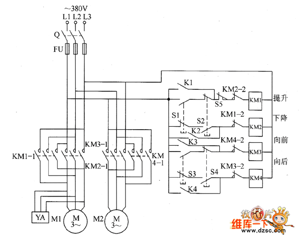
The remote control electric hoist control circuit comprises a wireless transmitter, a wireless receiver control circuit, and a main control circuit. The wireless transmitter utilizes the TWH9326 four-key BP transmitter. The wireless receiver control circuit includes a power supply...
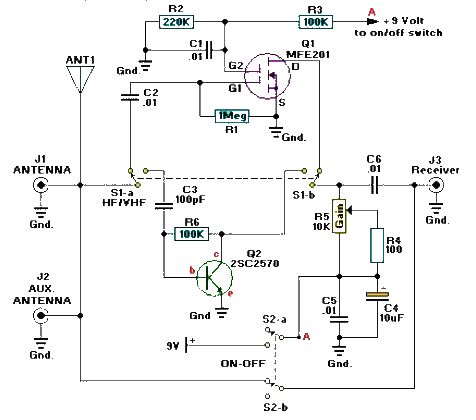
A simple and efficient active antenna electronic project can be designed using this electronic schematic circuit based on transistors. This active antenna project is effective for a wide range of RF frequencies, covering three RF bands: HF, VHF, and...
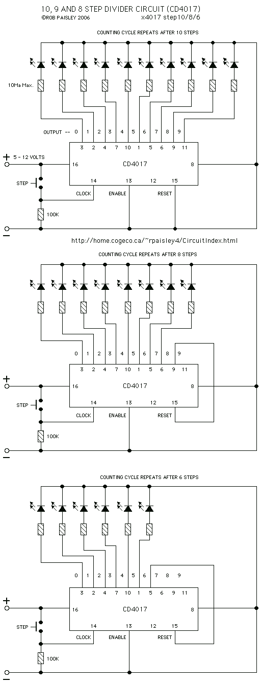
Each time switch S1 is closed the count on the CD4017 advances by 1 step and the corresponding LED turns on. When the maximum count plus 1 is reached for each circuit the cycle is restarted and repeats. The circuit...
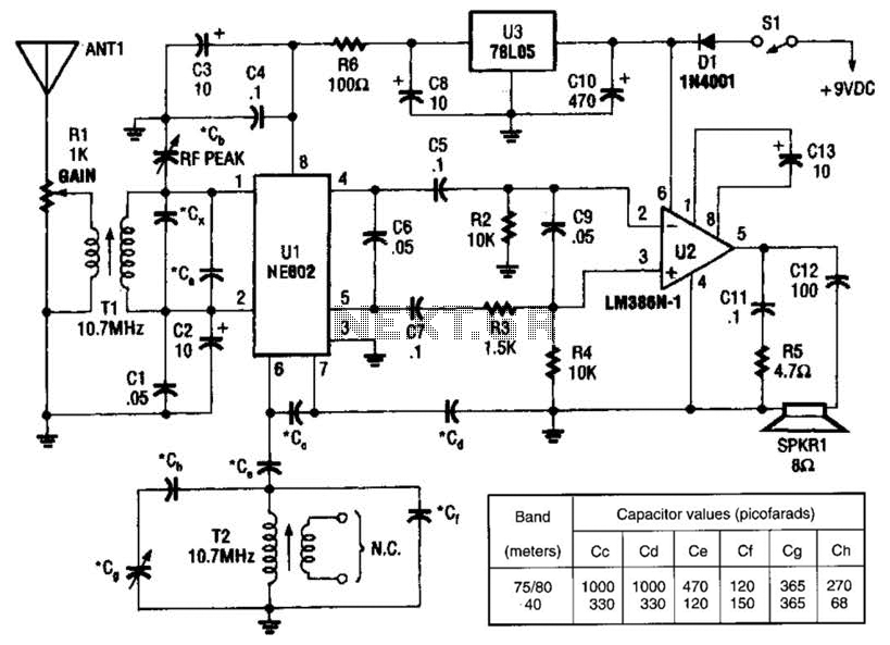
An NEC602 is utilized as a mixer with a zero intermediate frequency (IF) output, while U2 functions as an audio amplifier. This receiver is mainly designed for single sideband (SSB) and continuous wave (CW) signals. T1 and T2 are...
This type of infrared proximity circuit is commonly utilized as an electric switch where physical contact is undesirable for hygiene reasons. For instance, infrared proximity sensors are frequently found in public drinking fountains and washrooms. The straightforward circuit described...
One type of tone regulator is the audio graphic equalizer, which can be categorized into two types: the audio graphic equalizer bar and the parametric equalizer. This article focuses on the bar type, specifically a 5-channel equalizer utilizing the...