
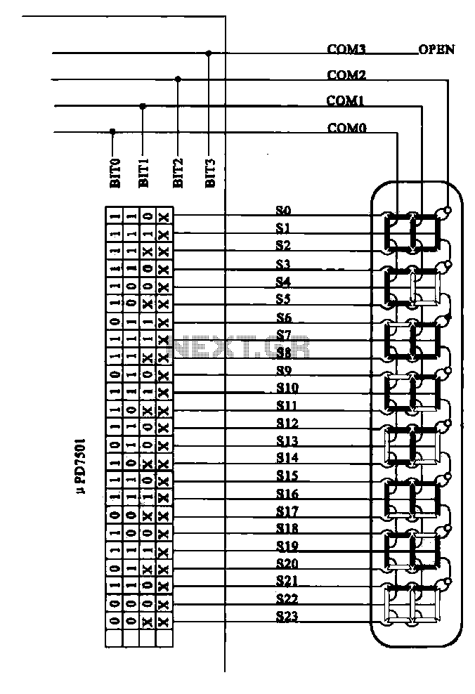
CPU number of liquid crystal display driver circuit example tube
Liquid crystal display (LCD) drive circuits play a critical role in controlling the operation of LCD panels, which are widely used in various electronic devices. These circuits typically consist of a combination of integrated circuits (ICs), passive components, and sometimes microcontrollers, which work together to manage the voltage and timing necessary for the proper functioning of the LCD.
The primary function of an LCD drive circuit is to generate the necessary waveforms that control the alignment of liquid crystal molecules in the display. This is achieved through a series of voltage levels applied to the electrodes of the LCD. The drive circuit must be capable of producing different waveforms for different pixel states, ensuring that the display can represent various images and text clearly.
In a typical LCD drive circuit, a microcontroller or dedicated LCD controller IC interfaces with the CPU to receive image data. This data is processed and converted into specific control signals that determine the on/off state of individual pixels. The drive circuit may include components such as resistors, capacitors, and transistors to shape the output signals and manage the timing for refreshing the display.
Moreover, the design of the LCD drive circuit can vary depending on the type of LCD technology used, such as twisted nematic (TN), in-plane switching (IPS), or organic light-emitting diode (OLED). Each technology may require different driving voltages and signal timings, which must be accounted for in the circuit design.
In summary, the structure of an LCD drive circuit is essential for the effective operation of liquid crystal displays. It integrates various components to ensure precise control over the display's performance, enabling high-quality visual output in electronic devices.Examples of the structure of a number of liquid crystal display drive circuit CPU tubes.
Related Circuits

Figure 1 illustrates an economical and straightforward Gate Alarm designed to operate using a small universal AC-DC power supply. IC1a functions as a fast oscillator, while IC1b serves as a slow oscillator. These two oscillators are integrated through IC1c...
The goal is to utilize a PC to measure the outdoor temperature using a serial-connected device equipped with a probe that can be conveniently placed outside. Although various options were found through online searches, many appear to be overly...
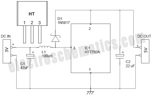
There are several methods to convert an AC voltage from a wall receptacle into the DC voltage required by a microcontroller. Traditionally, this has been accomplished using various types of power supply circuits. To convert AC voltage to DC voltage...
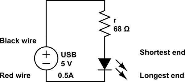
The LED operates at 3V, and based on information available online, a blue LED typically supports a maximum current of 0.03A. Given the available current from the USB source, the intention is to construct a parallel circuit. However, the...
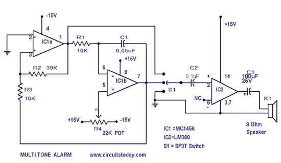
A simple alarm circuit with a diagram and schematic that generates a multi-tone sound. This alarm circuit is suitable for use in burglar alarms and sirens and is designed using dual op-amps MC1458 and LM380. The described alarm circuit utilizes...
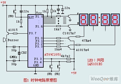
The circuit design incorporates an anodic Nixie tube for the LED display. It utilizes the LQ5101BS general luminous diode, with the driving transistor being either the 2SA1015 or 2SC1815 types, which are readily available. Additionally, low-power transistors such as...