
Schematic diagram of clock circuit composed of AT89C2051

The circuit utilizes an anodic Nixie tube as the primary display element, which operates by illuminating specific segments to represent numerical values. The LQ5101BS general luminous diode serves as the light source, providing adequate brightness for visibility. The driving transistors, either the 2SA1015 or 2SC1815, are selected for their availability and reliability in switching applications. These transistors control the current flowing through the Nixie tube, ensuring that the segments light up correctly based on the signals received from the microcontroller.
Alternative low-power transistors, including the S9012, S9013, S9014, 2N5401, and 2N5555, can be employed if the design requires components with different specifications or performance characteristics. These transistors are suitable for driving low-current applications, making them ideal for use in conjunction with the Nixie tube.
The AT89C2051 microcontroller is an essential part of this circuit, and its integration is facilitated by the DIP20P socket, which simplifies the connection process. This microcontroller is particularly advantageous due to its flash memory capability, allowing users to write and rewrite programs easily without the need for extensive debugging. This feature is beneficial for rapid prototyping and experimentation, as it enables quick iterations of program modifications.
The overall design is straightforward, with no stringent requirements for additional components, making it accessible for experimentation and educational purposes. The combination of the Nixie tube display, the selected driving transistors, and the programmable microcontroller creates a versatile circuit that can be adapted for various applications in electronic learning and prototyping environments.The circuit composition determines that the LED adopts anodic Nixie tube. It can use LQ5101BS general luminous diode and the driving triode can use 2SA1015 or 2SC1815 types which is easy to gain. Of cause, the triode can also use low-power triode such as S9012, S9013, S9014, 2N5401, and 2N5555 etc.
There are no special requirements for other componen ts. To make the experiment easier, monolithic AT89C2051 can use DIP20P socket. The program need no debugging after written, and it can be copied to AT89C2051. What worth mentioning is that AT89C2051 is a flash program memorizer, and the program can be rewritten repeatedly, which makes it very easy to conduct experiments. 🔗 External reference
Related Circuits
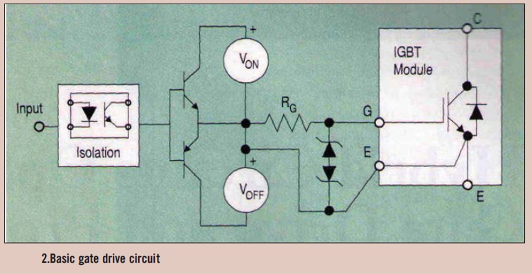
High power IGBT modules utilize hybrid integrated circuit (IC) gate drives that incorporate protection circuits, which implement desaturation detection or real-time control. High power Insulated Gate Bipolar Transistor (IGBT) modules are essential components in various high-efficiency power conversion applications, such...
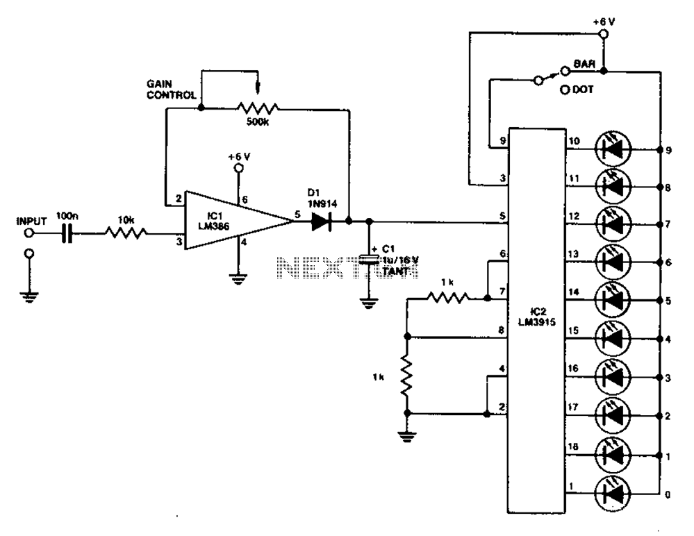
A simple level power meter designed to provide a high-fidelity sound system with a bar or dot matrix display. The green LED display indicates levels from 0 to 7; level 8 is shown in yellow, and level 9 is...
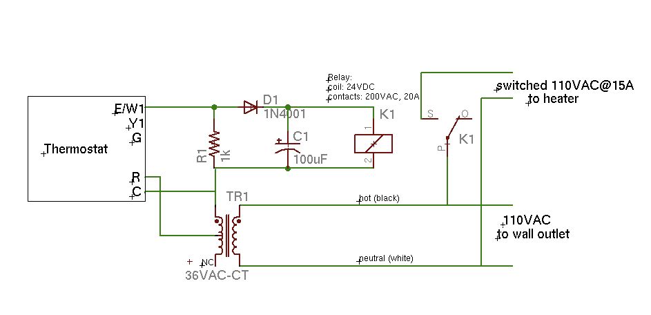
A basic schematic of the circuit is presented, marking the initial experience with Eagle software. It is important to note that only the W1 output of the thermostat is utilized, while C serves as the common connection. The schematic outlines...
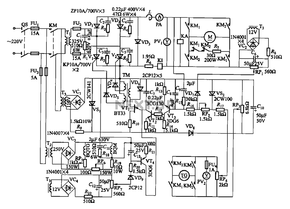
The circuit encompasses a main circuit, a trigger circuit, speed negative feedback, negative feedback differential voltage, a current cut-off circuit, loss of field protection, and other components. Given that the motor power is small (1.1 kW), a single-phase circuit...
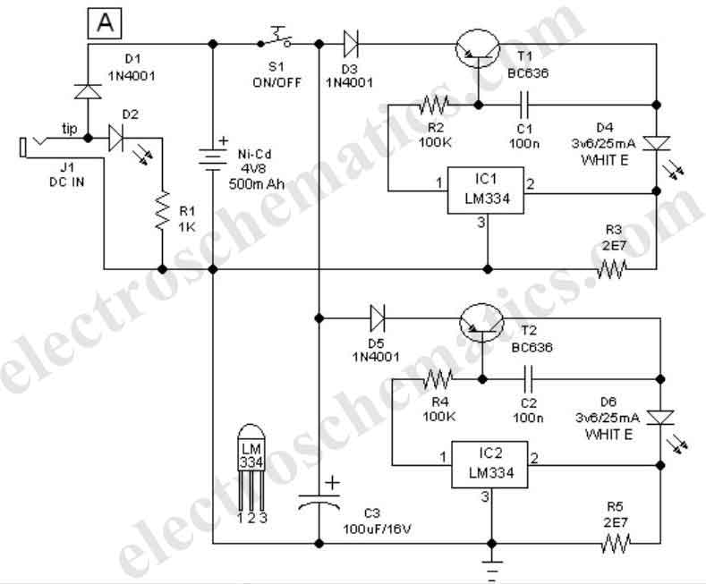
This easy-to-construct handy pen torch electronic circuit has a low component count and utilizes two power white LEDs for illumination. A low voltage (4.8V DC) supply is derived from a built-in rechargeable Ni-Cd battery pack and is converted into...
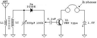
The following schematic illustrates a Crystal Radio Receiver Circuit Diagram that incorporates audio frequency (AF) amplification utilizing a Germanium transistor. The inclusion of AF amplification enhances the audio output quality. The Crystal Radio Receiver Circuit is a simple yet effective...