
Vibration Detector Circuit
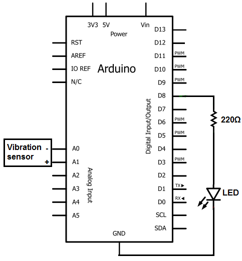
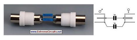
This circuit is used often for impact sensing or as a flexible switch. If the piezo sensor is flexed, a large voltage will be created which can switch on a transistor, SCR, or any other type of switching device. The piezo vibration sensor is from the company MEAS. It can be obtained from a number of online retailers for a very low price (under $5). Follow this link to the piezo sensor offered by Sparkfun- Sparkfun- Piezo vibration sensor. We will connect the 2 pins to analog terminal A0 and A1 of the arduino board. We will then in our code set one to LOW, representing ground, while the other pin will be the sense pin, which will sense for any vibrations that are made in the sensor`s vicinity.
The piezo sensor works very well with the arduino. It 2 pins simply go into analog terminal A0 and A1 of the arduino. A0 will be configured to be ground and A1 will be the positive sense pin of the vibration sensor. This pin will detect whether there is any vibration or not. The LED`s positive pin (the anode) will go into digital pin 13 of the arduino and the negative or ground lead (the cathode) will be connected to ground. No resistor needs to be connected in series with the LED because digital pin 13 has built-in resistance.
Therefore, there is enough resistance intrinsically to limit current going to the LED, such that no external resistor is necessary. Now that we have our circuit setup, we now just need to connect the arduino to a computer via a USB. The type A connector goes into the computer and the type B goes into the arduino. The first block of code defines the pin connections. The ground pin (of the sensor) will be put in A0 of the arduino. The sensepin will be placed in A1. And the LEDPin will be placed in digital pin D13. The second block of code defines a variable called threshold. This is a very important variable because it represents the analog level at which the LED will be triggered to turn on.
The arduino can detect and measure analog values from 0 to 1023. We created it so that once an analog sound vibration reaches 500 or greater, the LED will be triggered on. You can modify this value to be less or greater depending on the amplitude of the vibration you want to be the trigger point.
However, a value near 500 is good for all practical purposes. If you lower the threshold value, then the circuit will detect vibrations easier. If you raise the threshold value, the circuit will need greater vibrations in order to trigger. The third block of code sets up the A0 terminal as the ground pin. It must be set as output and then declared LOW in order to function as a ground. This serves as the ground for the negative lead of the piezo sensor. The LEDPin serves as a digital output pin for the LED we connect to D13, so it must be declared output. We put the line Serial. begin(9600) so that if we want, you can see the values that the arduino is reading from the sensor if you had the line Serial.
println(reading), for testing purposes. The fourth block of code is the loop() function. The reading variable measures the actual voltage on the sensePin of the vibration sensor, which is the positive terminal connected to A1. If the reading is larger than the threshold value, the LED will be triggered to high and turned on. If not, it does not turn on. With this code, we only turn the LED on when the vibration is a large enough amount. If you want, you can set the threshold to a higher amount, so that the LED only turns on for a greater impact force to the sensor.
Play around with this to suit your needs. And this is how a vibration sensor works integrated with an arduino board. With this circuit, the LED will turn on for a second with each vibration above the given threshold and then turn off. Again, several variations of this circuit can be done to fit your needs. Maybe you don`t want an LED to light when vibration is detector. Maybe you want a buzzer to sound. In that case, you replace the LED with a buzzer. Maybe you don`t want a buzzer. You want a fan to go off. There are many ways the circuit can operate. Customize according to your needs. 🔗 External reference
Related Circuits

The working and block diagram of the IC 723 Voltage Regulator is provided along with the circuit diagram and applications. The IC 723 is a voltage regulator integrated circuit that is widely used for providing a stable output voltage. It...
The ignition coil driver circuit described is a highly regarded design, reportedly created by Jochen Kronjaeger. It is intended to operate from a 230V source, although a modified version can function effectively at 120V. The circuit requires two ignition...
It's very simple actually. The idea is that we use what we have learned from the capacitor tests to create a circuit that uses the capacitors to run the load and then by discharging the 1/2 full capacitor into...

This circuit utilizes a photoelectric coupler to achieve 100GΩ isolation between a TTL (Transistor-Transistor Logic) circuit and a relay circuit. This configuration effectively prevents relay noise and peak voltage from affecting the TTL circuit. When the TTL input signal...

This is a simple portable audio amplifier circuit. The circuit is built around the TEA2025 integrated circuit, which is a monolithic audio amplifier housed in a 16-pin dual in-line package manufactured by UTC. The circuit features an internal thermal...
Nowadays, an increasing number of audio-visual devices in homes are interconnected. This is particularly true for televisions, which may be linked to DVD players. In modern home entertainment systems, the integration of various audio-visual devices enhances user experience and convenience....
Warning: include(partials/cookie-banner.php): Failed to open stream: Permission denied in /var/www/html/nextgr/view-circuit.php on line 713
Warning: include(): Failed opening 'partials/cookie-banner.php' for inclusion (include_path='.:/usr/share/php') in /var/www/html/nextgr/view-circuit.php on line 713