
Crossfeed Audio
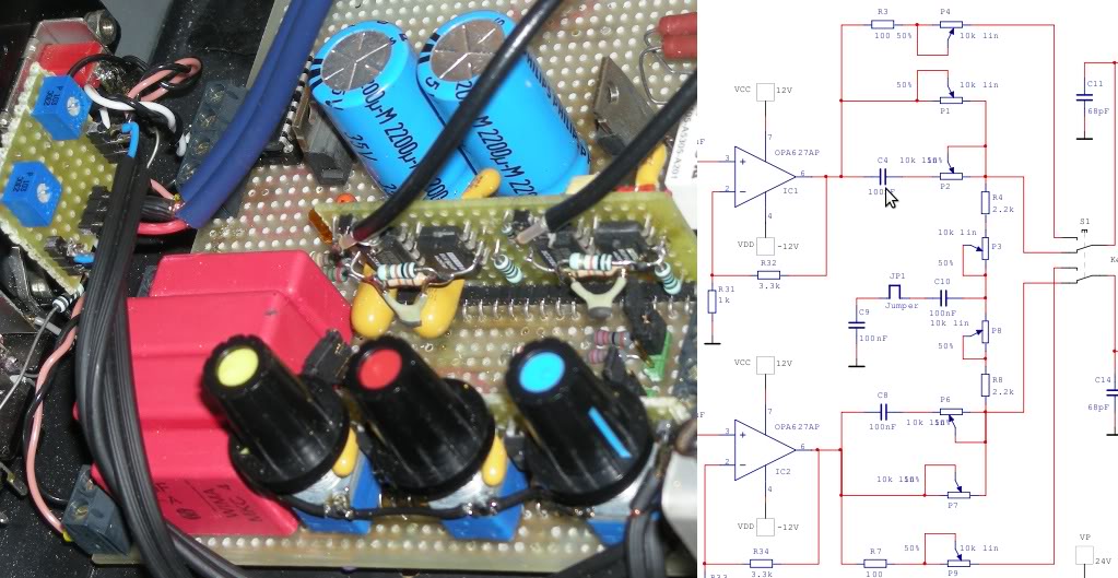
The Linkwitz crossfeed circuit is an innovative approach to enhance the listening experience by simulating the natural sound dispersion that occurs when listening to music in a room. The circuit aims to reduce the harshness of stereo imaging that can result from headphones, which often create an exaggerated separation of audio channels. By blending a small amount of the signal from one channel into the other, the crossfeed circuit helps to create a more cohesive soundstage, making the audio more natural and immersive.
The basic components of a Linkwitz crossfeed circuit typically include operational amplifiers (op-amps), resistors, and capacitors. The circuit design involves configuring the op-amps to process the left and right audio signals, allowing for controlled mixing. The resistors set the levels of crossfeed, while capacitors can be used to shape the frequency response, ensuring that the blend of channels does not compromise the fidelity of the audio.
When constructing the circuit, careful attention should be paid to component selection and layout to minimize noise and distortion. Power supply decoupling is also crucial to maintain signal integrity. The circuit can be implemented in various formats, including standalone units or integrated into headphone amplifiers.
Overall, this project not only serves as an engaging hands-on experience but also provides valuable insights into audio processing techniques that can significantly enhance headphone listening experiences.Here`s a simple and fun project / circuit in case you would like to try crossfeed. It`s based on a Linkwitz crossfeed. There is a big difference in crosstalk and crossfeed (a.k.a. X-feed). Crosstalk is a technical term for bad channel (left and right) separation. Like the sort you get with vinyl and sometimes tape. 🔗 External reference
Related Circuits
The Tiny Audio Amplifier kit is a good choice for battery operation. It is based on LM386 IC. Power supply - 6 - 12 VDC. Output power - 1 W, 8 Ohm. The quiescent power drain is only 24...
As shown in the figure, the 555 timer, resistors R1, RP1, and capacitor C1 form a controlled audio oscillator. The frequency of the oscillator is given by the formula f = 1.44 / ((R1 + 2 * RP1) *...
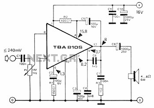
This circuit is a 7 Watt audio amplifier that is simple and easy to construct. It utilizes the TBA810 as the primary component, supported by a few passive components. The amplifier operates effectively, and the necessary kits and components...
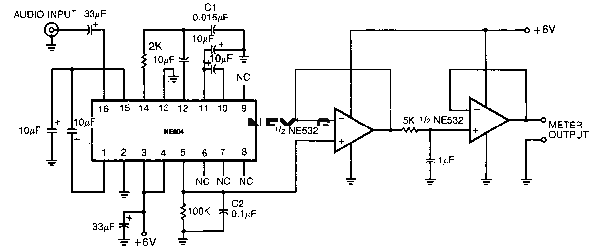
This circuit consumes very little power, drawing less than 5 mA from a single 6-V power supply, making it suitable for portable battery-operated devices. Its compact size and low power consumption do not compromise its performance, offering a dynamic...
The circuit presented is a 20W audio amplifier utilizing the LM1875 integrated circuit (IC). The LM1875 is a high-quality, low-distortion audio amplifier IC rated for 20 watts, available in a TO-220 package. This IC includes several built-in features such...
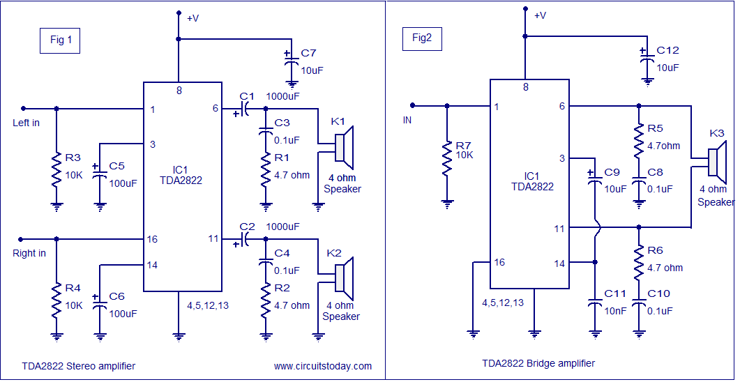
The TDA2822 audio amplifier circuit provides 1.35W output into a 4-ohm speaker when powered by a 6V supply. It supports both bridge and stereo modes and operates within a supply voltage range of 3V to 15V, making it suitable...