
Rf driver audio oscillator circuit diagram
The audio oscillator circuit utilizes the 555 timer in astable mode, which enables continuous oscillation and generation of a square wave output. The configuration consists of a 555 timer IC, two resistors (R1 and RP1), and a capacitor (C1). The timing components, R1 and RP1, along with C1, determine the frequency of oscillation, allowing for a wide range of audio frequencies suitable for various applications.
In this circuit, R1 is a fixed resistor, while RP1 is a variable resistor (potentiometer), which provides the flexibility to adjust the oscillation frequency. The capacitor C1 acts as the timing capacitor, and its value, in conjunction with the resistors, directly influences the charge and discharge times, thus affecting the frequency output.
The formula f = 1.44 / ((R1 + 2 * RP1) * C1) indicates that the frequency is inversely proportional to the total resistance and capacitance in the circuit. By increasing the resistance of RP1, the frequency decreases, allowing for lower audio tones, while decreasing the resistance raises the frequency, producing higher tones. This range of 600 Hz to 20 kHz encompasses the audible spectrum, making the circuit suitable for applications such as tone generation, sound synthesis, and audio signal modulation.
The output from the 555 timer can be used to drive speakers or other audio devices, and additional filtering or amplification stages can be included in the design to enhance audio quality or drive larger loads. Proper selection of components is crucial to ensure stability and performance across the desired frequency range.As shown in the figure, 555, Rl, RPland C1form thecontrolled audio oscillator, f = 1.44 / ( R1 +2 RP1) C1, the icon parameter frequency isbetween 600Hz ~ 20kHz, and it can beselected by adjusting RP1.. 🔗 External reference
Related Circuits
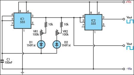
This timer utilizes two 555 integrated circuits (ICs) to adjust the desired output. The variable resistors VR1 and VR2 serve as potentiometers to modify the cycle speed. The circuit can be powered with a 9 to 12-volt power supply,...
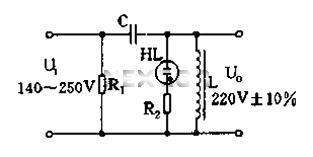
Easy exchange of magnetic saturation voltage regulator circuit The magnetic saturation voltage regulator circuit is designed to stabilize output voltage levels by utilizing magnetic saturation principles. This circuit typically employs a magnetic core, which operates in saturation to regulate...
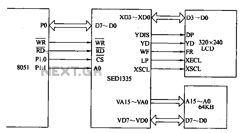
The MCS-51 series single-chip interface circuit 8051 is utilized to control the SED1335 35 dot matrix LCD display. This controller can manage up to a 640x256 dot matrix LCD display for both graphics and character representation, with the capability...
The ICL7107 is a 3 1/2 digit LED analog-to-digital converter (A/D converter). It features an internal voltage reference, high-isolation analog switches, sequential control logic, and display drivers. The ICL7107 is designed to convert analog signals into digital representations with a...
In this circuit, a simple calculator, in conjunction with a COB (chip-on-board) from an analogue quartz clock, is used to make a telephone call meter. The calculator enables conversion of STD/ISD calls to local call equivalents and always displays...
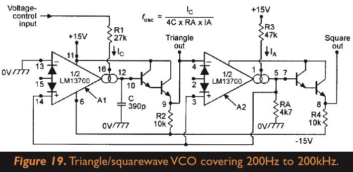
The circuit generates square and triangle waves. There is an inquiry about the possibility of adding a couple of diodes and a potentiometer to enable skewing between triangle-ramp/saw and changing the duty cycle of the square wave. Is it...