
Crosswalk Pedestrian Signal and Homemade Controller
The described signal system is a pedestrian traffic control device that integrates a countdown feature for improved user understanding of the timing for crossing. The three wires—common, "walk," and "don't walk"—serve distinct functions essential for the operation of the signal. The microcontroller embedded within the unit is critical for its autonomous operation, allowing it to measure and adapt to the timing of the "walk" phase without requiring external timing signals. This self-contained functionality ensures that the countdown display remains synchronized with pedestrian crossing intervals, which enhances safety and usability.
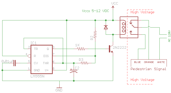
The timing mechanism relies on the stability of the "walk" phase duration, necessitating a consistent input from a timer circuit. The implementation of a 555 timer in astable mode offers a straightforward solution, allowing for adjustable pulse widths that can be tailored to meet specific timing requirements. The choice of components, particularly the capacitor and resistors, directly influences the timing intervals for the "walk" and "don't walk" signals. The use of a relay to switch between these states is a common practice in traffic signal design, ensuring reliable operation under varying conditions.
Safety considerations are paramount due to the involvement of AC mains power. Proper enclosures and adherence to electrical safety standards are essential to prevent hazards. The flexibility in supply voltage allows for compatibility with a wide range of relay types, facilitating the selection of components that best suit the application.
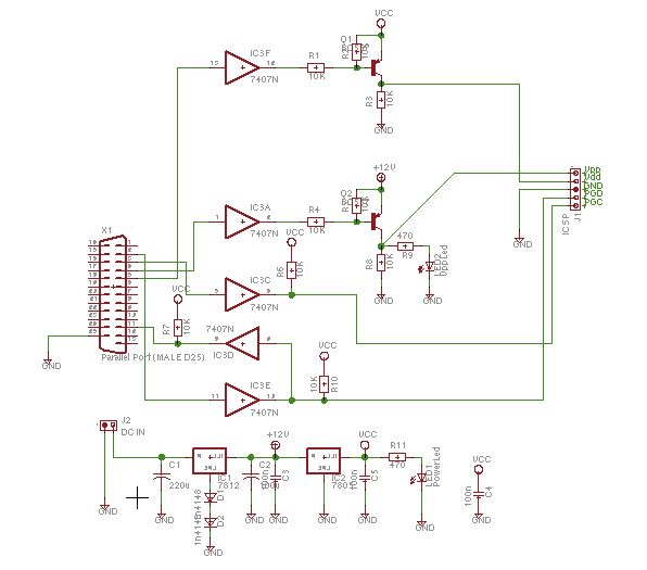
As the design evolves to incorporate a microcontroller like the Atmel AVR ATtiny44, additional features such as programmable timing intervals, remote monitoring, and integration with smart traffic management systems could be introduced. This advancement would pave the way for more intelligent traffic control solutions, enhancing pedestrian safety and optimizing traffic flow in urban environments.The signal has three wires: common, "walk", and "don`t walk". This page describes the operation of the unit`s countdown feature. The information and examples provided here should work for other models and brands of signals. Click here togo to the beginning of the article The signal was shipped along with a two-page sheet detailing the use of the countdown timer. You can download a scan of the document here, but I will summarize the details here. The signal was designed to be a drop-in replacement for non-countdown signals. Instead of receiving timing information (such as the length of the countdown or even a separate signal to trigger it), the signal is intelligent and contains a microcontroller that times the length of the "walk" phase and inserts an appropriately-lengthed countdown automatically. This means that the signal needs to be controlled carefully; the length of each "walk" phase cannot change, or else the signal`s countdown will become confused and misaligned.
So, if you want the signal to display a 60-second countdown, then the "walk" phase must be exactly one minute in duration every time. In other words, you cannot control the countdown if you are using a manual (hand) switch. You need to use a timer that can provide consistent walk and don`t walk phases. When the signal is powered up, its internal microcontroller will measure the duration of the length of the "walk" phase.
It takes the signal two walk/don`t walk cycles to adapt to and measure the time intervals; only after the second cycle does the countdown come on. The microcontroller that runs the display digits and times the phases is powered whenever either the hand or man is illuminated.
However, when power is completely removed from the display, the microcontroller forgets the timing details that it had measured. This means that each time the pedestrian light is turned off and turned back on, the signal must re-do the timing routine described above.
This is rather annoying, but understandable because it would be foolish to use non-volatile memory on a signal that would typically run 24/7 on a street corner. A timer circuit that meets the above requirements is so simple that can be built with just a 555 timer IC, a relay, and the appropriate supporting components.
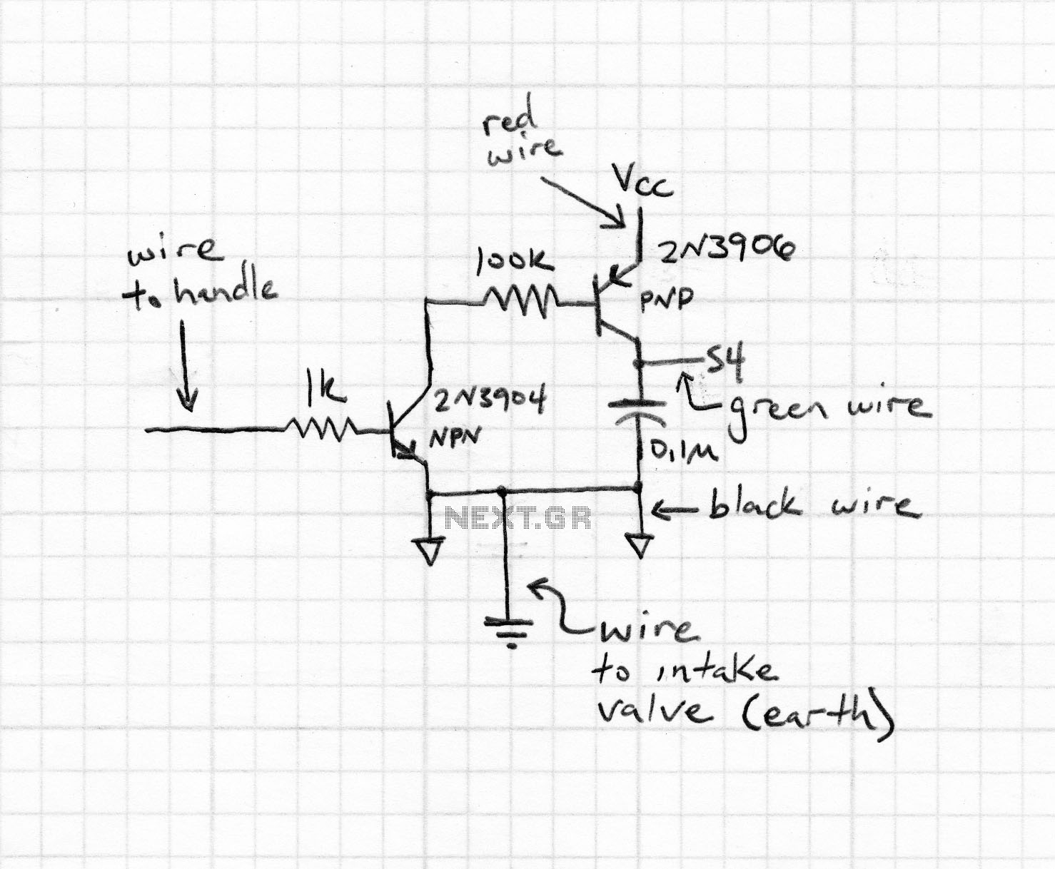
No microcontroller is necessary, although I`ll implement one later in the article. Here is the schematic. It consists of a 555 in pulse generation (astable) mode, with a large capacitor to make 30-120 second pulses that drive a relay, which in turn switches between "walk" and "don`t walk". To provide an interval of 15 seconds "walk" and 30 seconds "don`t walk", use: C1 = 220 µF, R2 = 100k ©, R3 = 100k ©.
Feel free to experiment with the exact values. Also, this circuit involves the use of AC mains power. This project, if attempted, must be encased in a secure and safe enclousure. Take all standard safety precautions and do not attempt if you are uncomfortable with the risks. I accept no liability. The supply voltage (Vcc) of this circuit is flexible: anywhere from 5-12 V should be fine. Use whatever voltage matches the coil voltage (5, 6, 9, 12V are very common) of the relay you select. To increase functionality and features, I decided to build a microcontroller-based controller using an Atmel AVR ATtiny44.
Go to the next page to continue reading. 🔗 External reference
Related Circuits
A simple and interesting project schematic for a cell phone signal-activated LED circuit. The circuit will illuminate an LED when a call is made from a cell phone. This cell phone signal-activated LED circuit utilizes a basic principle of detecting...
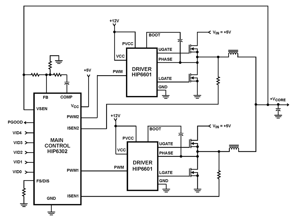
The HIP6302 Multiphase PWM control IC, along with its companion gate drivers (HIP6601, HIP6602, or HIP6603) and Intersil MOSFETs, delivers a precise voltage regulation system for advanced microprocessors. Multiphase power conversion represents a significant advancement over traditional single-phase converter...
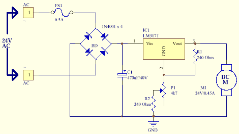
This information pertains to a dosing pump control circuit that utilizes the LM317 integrated circuit (IC). The circuit operates with a power supply of 24V DC and is capable of adjusting the output voltage to 1.25V. The LM317 is a...
Upon entering the password, the application, in this case "LED," will illuminate. In this digital locking system project, the interfacing of a keypad and a 16x2 LCD with a microcontroller will be explored, along with the accompanying code. This...
Schaer is a generic programmer circuit capable of uploading and downloading firmware to and from several electronic devices, such as microcontrollers. The Schaer programmer circuit is designed to facilitate the transfer of firmware between a host computer and various electronic...
The BPS Servo Controller - Digital is a comprehensive metering and control solution designed for servo stabilizers, accommodating a wide range of input voltages and load requirements. This system minimizes production overheads such as wiring and testing, thereby enhancing...