
Password(code) Based Digital Locking System Using Microcontroller 89C52/89S52
The digital locking system described utilizes a microcontroller as the central processing unit, interfacing with a 4x4 matrix keypad and a 16x2 LCD display. The keypad serves as the input device, allowing users to enter a numeric password, while the LCD provides visual feedback throughout the process. The microcontroller is programmed to initialize the display upon power-up, first showing the "password based" message, followed by the prompt to "enter password."
The microcontroller requires a minimal setup, including a crystal oscillator to provide a stable clock signal and a switch for reset functionality. The power supply should be stable and within the operating range of the microcontroller to ensure reliable performance.
The software logic implemented in the microcontroller's firmware includes a loop that waits for user input from the keypad. Each digit entered is masked with an asterisk to maintain security. Upon entering the four-digit password, the firmware compares the input against a predefined value (defaulting to 1234). If the input matches, the LCD displays "correct password," and the LED connected to one of the microcontroller's output ports is activated, indicating successful access.
To allow for customization, the password can be easily modified in the code. By adjusting the variable that holds the password value, the user can set a new password as desired. Furthermore, the design can be expanded to accommodate longer passwords by implementing additional loops in the code, thus enhancing security.
Overall, this digital locking system project serves as an educational tool for understanding the integration of input and output devices with a microcontroller, as well as the fundamentals of embedded programming and circuit design.entering of the password, the application as in this case "led" will glow. In this Digital locking system project you will learn more about interfacing keypad and 16x2 LCD to your micro controller along with the code. Since this project has been made in proteus software you must have a prior knowledge of it. If you are unaware of the software here is a tutorial which i recommended in one of my previous articles. Other components like the crystal and switch are connected for the working of the microcontroller ( minimum circuitry required for proper working of the microcontroller). As soon as the power supply is provided to the microcontroller "password based" will be shown on the screen.
This will remain for a second and after that "enter password" will be displayed as shown below. The "ENTER PASSWORD " statement will remain for a second and then it will vanish. At this point you will have to enter password which will be shown in terms asterisk " * ". The coding of the micro-controller is done such that only four numbers can be used to enter password. If you want to increase the length of the password you can do that by adding loops in the coding which will be dealt later.
Here, in this project the password is set as 1234. when this password is entered the LCD will display "correct password" as shown below and the LED will turn on which is connected at port 1. you can set your own password by changing the password in the code. 🔗 External reference
Related Circuits
The reason why I am using an LCD display is because it allows me to display many characters and it doesn't need to be refreshed as 7-segment LED displays. Also, the interface requires less I/O pins. For this project,...
.png)
Have you ever considered implementing your own home security alarm system? It is one of the simplest and most interesting circuits for electronics beginners. The new home security equipment utilizes a Light Dependent Resistor (LDR) to detect security breaches....
Some still remember the serial RS232 port, also referred to as a COM PORT, as its functionality has largely been replaced by USB ports. However, for electronics engineering students and technicians learning about computer interfaces, the RS232 port remains...

This 555 timer circuit temperature monitoring system project can monitor temperature at up to four points. The system allows for the selection of whether the alarm should be triggered when the temperature increases or decreases, depending on the resistance...
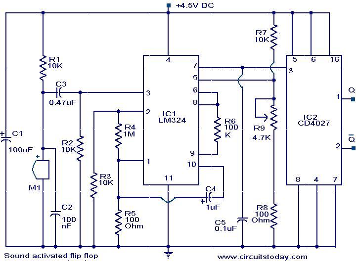
The following circuit illustrates a Sound Operated Flip Flop. This circuit is based on the LM324 integrated circuit. It features a condenser microphone used for sound detection. The Sound Operated Flip Flop circuit utilizes the LM324 operational amplifier, which consists...
This document presents an electronic project focused on device control using a timer. This circuit allows for the activation of an appliance at a specified time for a predetermined duration. It can be applied to manage the operation of...