
Cruise Control Removal
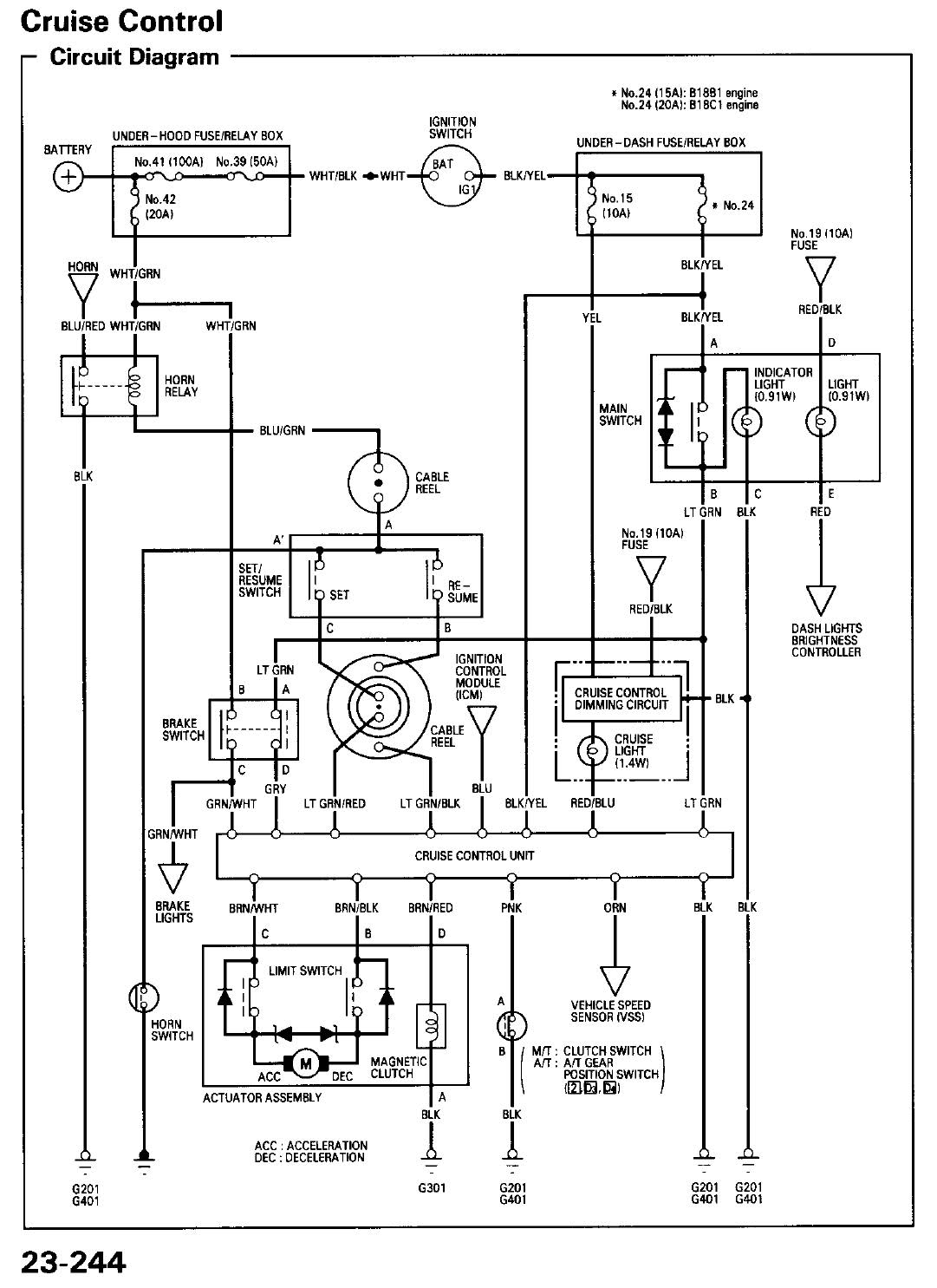
The cruise control system in vehicles typically consists of several key components, including the cruise control switch, the throttle actuator, the vehicle speed sensor, and the engine control unit (ECU). The wiring diagram for a cruise control system provides a visual representation of how these components are interconnected and how they communicate with each other.
In a standard cruise control setup, the cruise control switch is usually located on the steering wheel or stalk. When activated, this switch sends a signal to the ECU, which processes the input and engages the throttle actuator. The throttle actuator is responsible for adjusting the throttle position to maintain the desired speed set by the driver.
The vehicle speed sensor plays a critical role by providing the ECU with real-time data on the vehicle's speed. This information allows the ECU to make necessary adjustments to the throttle actuator to ensure that the vehicle maintains the set speed. The wiring between these components typically involves power and ground connections, as well as signal wires that transmit information between the switch, ECU, throttle actuator, and speed sensor.
To create a comprehensive wiring diagram, it is essential to include the pin assignments for each component, the color codes for the wires, and the connection points on the ECU. This information is crucial for troubleshooting and repair, as it allows technicians to identify issues within the cruise control system effectively. Additionally, safety considerations should be noted, as improper wiring can lead to malfunctioning systems that may compromise vehicle safety.
Overall, a detailed wiring diagram for cruise control in vehicles from 1994 and onward is essential for understanding the system's operation and for effective maintenance and repair.well i did a quick search, and i didnt find much on this issue my question is: Can anyone provide a diagram on how cruise control is wired up (94-.. 🔗 External reference
Related Circuits
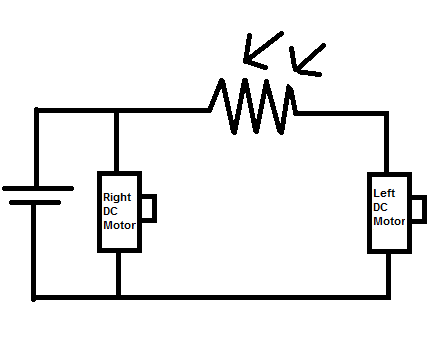
Construct a toy device that spins to the left whenever there is an obstruction in front of it, without utilizing a microcontroller. The proposed design involves using two DC motors as the rear wheels. An LDR (Light Dependent Resistor)...
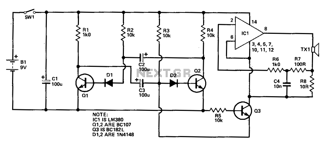
Many audio systems consist of separate units, where typically only the amplifier is equipped with a remote control receiver module for economic reasons. Control signals are then transmitted to other units using patch cables. For instance, the tuner and...
This circuit comprises two fundamental components: an oscillator tuned to 40 kHz and a voltage doubler with a pulse generator. The pulses generated are approximately 10 ms in duration and occur 2-3 times per second to minimize battery consumption...
The LED guard-rail tube, also known as the decorative tube, is an advanced LED illumination product designed for decorative purposes. It utilizes red, green, and blue LEDs as light sources, employing microelectronics and digital technology to create color chasing...
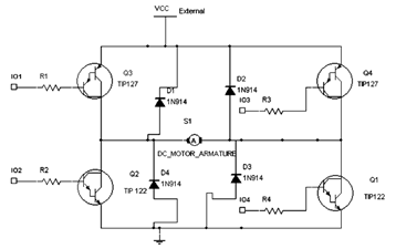
The diagram below illustrates an H-Bridge circuit featuring four inputs and an external power supply. The control application must enable the motor to operate in both forward and reverse directions. The H-Bridge is a crucial component in motor control applications,...
This circuit could be used for replacing your manual volume control in a stereo amplifier. In this circuit, push-to-on switch S1 controls the forward (volume increase) operation of both channels while a similar switch S2 controls reverse (volume decrease)...
Warning: include(partials/cookie-banner.php): Failed to open stream: Permission denied in /var/www/html/nextgr/view-circuit.php on line 713
Warning: include(): Failed opening 'partials/cookie-banner.php' for inclusion (include_path='.:/usr/share/php') in /var/www/html/nextgr/view-circuit.php on line 713