
IR Remote Control Receiver
The described circuit operates as an interface for integrating remote control functionality into audio systems that lack built-in IR receivers. The primary component is a standard IR receiver module that detects IR signals from a remote control. This module outputs a low signal when an IR command is received, which is then buffered and processed by the first inverter. The high impedance output of the IR module requires buffering to drive subsequent stages effectively, hence the inclusion of the inverter.
The second inverter stage allows for flexibility in the output signal, enabling the user to select between two signal configurations using jumper JP1. This feature is particularly useful in different setups where the polarity or type of signal required may vary. The resistors R1 and R2, along with the capacitor C1, form a critical part of the circuit protection and stability. R1/C1 acts as a filter to mitigate any voltage spikes that could potentially damage the circuit or the connected audio equipment. R2 serves as a current-limiting resistor, protecting the output from excessive current draw, which is especially important when interfacing with sensitive electronic devices.
The low power consumption of approximately 1 mA makes this circuit highly efficient for battery operation. The choice of power supply, whether rechargeable NiMH batteries or alkaline batteries, allows for flexibility based on user preference and environmental considerations. Overall, this circuit represents a practical solution for enhancing the functionality of standalone audio components, enabling remote operation without the need for built-in receivers.With many audio systems consisting of separate units, you`ll oftennd that due to economic reasons only the amplifier has a remote control receiver module. The control signals are then sent to the other units using patch cables. The tuner and CD player, for example, won`t have a built-in receiver module. When the tuner from such a system is bou ght separately it can therefore not be used directly with a remote control, which is a big disadvantage in practice. The only way in which this can be accomplished is to connect an IR receiver to the input used by the patch cable.
And that is exactly what this circuit is for. In practice it is not always clear which signal should be used and what its polarity should be. However, it will most likely be a demodulated signal. For these reasons we`ve combined a standard IR receiver module and two inverters. The first inverter also functions as a buffer, since the output of the module has a high impedance. The output of the receiver module is active low, so therst inverter outputs a non-inverting signal. The second inverter inverts this signal again. Jumper JP1 is used to select which of the signals is presented at the output. R2 protects the output from short circuits or possible over-loading of the electronics in the equipment it`s driving (for example when the input circuit uses 3 V logic). R1/C1 suppress any possible supply spikes. Batteries are suitable for the power supply, because the circuit only takes about 1 mA. With a set of four rechargeable batteries with a capacity of 1800 mAh the circuit can function continuously for 2.
5 months. Four NiMH cells and a charger are therefore perfect for the power supply. If you can be sure that the circuit will always be switched off when not in use, you could also use three ordinary alkaline batteries (AA cells). Because of their slightly larger capacity they will probably last for about half a year. When making your choice you should of course keep in mind that rechargeables are better for the environment.
🔗 External reference
Related Circuits
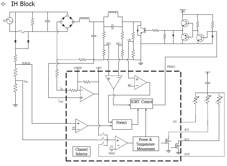
The control board features a 7-segment LED display for temperature and power readouts at the front. A fan is mounted at the base of the unit alongside an induction coil, which appears to use a similar gauge of Litz...
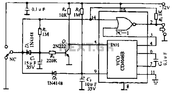
The figure illustrates a circuit involving dark tomb electric locks, specifically the fti: al: 4046B and XOR gate as the primary control mechanism. It emits pulses and utilizes silicon for successive pulse generation. The circuit operates with a normal...
This circuit disrupts the infrared receiver in a television by generating a continuous signal that interferes with the remote control signals, preventing the TV from recognizing channel changes or other commands. This allows for uninterrupted viewing of a chosen...
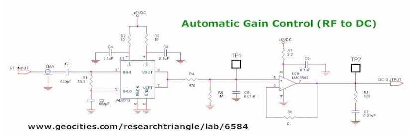
This project is a digital Automatic Gain Control (AGC) system using a PIC16F876 MCU. The ability to set the gain level in a circuit and have it control itself is a very useful function. This circuit is a building...
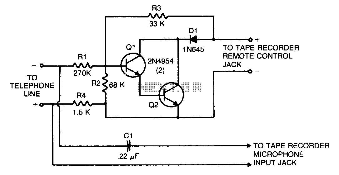
This circuit transforms a tape recorder into a fully automatic device for recording telephone conversations without requiring an external power source. The voltage at the switch terminals of the tape recorder is applied to a pair of Darlington-connected transistors,...
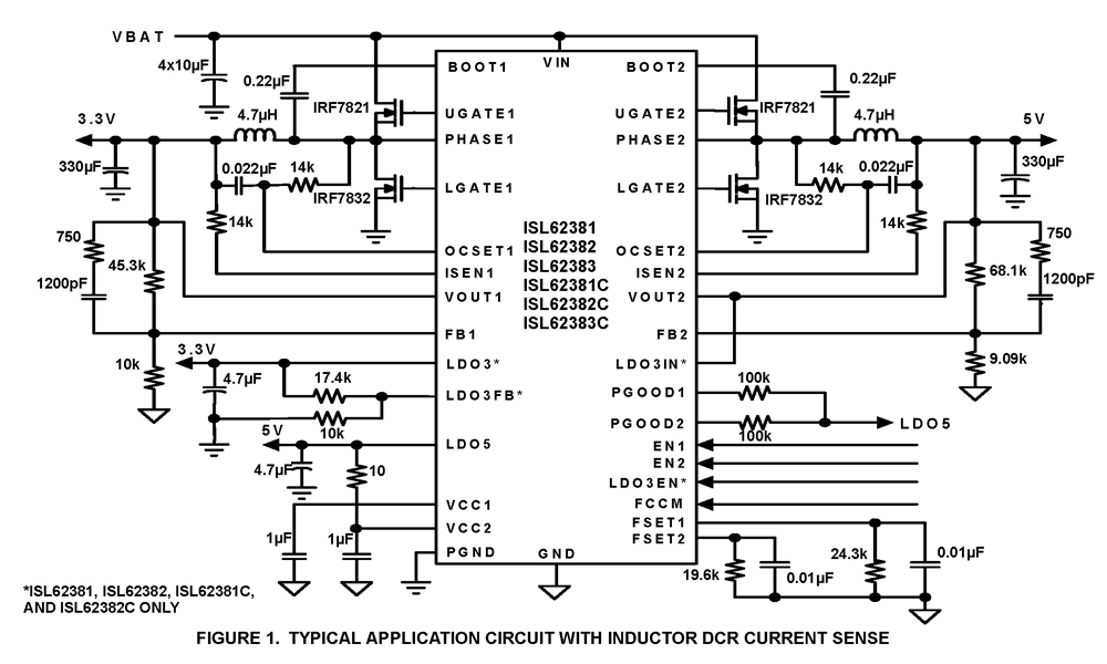
The ISL62381, ISL62382, ISL62383, ISL62381C, ISL62382C, and ISL62383C family of controllers generate supply voltages for battery-powered systems. These controllers include two pulse-width modulation (PWM) controllers, adjustable from 0.6V to 5.5V, and two linear regulators, LDO5 and LDO3, that generate...
Warning: include(partials/cookie-banner.php): Failed to open stream: Permission denied in /var/www/html/nextgr/view-circuit.php on line 713
Warning: include(): Failed opening 'partials/cookie-banner.php' for inclusion (include_path='.:/usr/share/php') in /var/www/html/nextgr/view-circuit.php on line 713