
Crystal Activity Tester Circuit
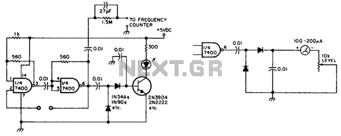
The circuit utilizes two sections of a 7400 NAND gate IC, configured to form a relaxation oscillator. The oscillator generates a square wave signal, which indicates the activity of the crystal under test. The output from the oscillator is fed into a rectifier circuit, typically consisting of a diode, to convert the AC signal into a DC voltage suitable for driving the next stage.
The rectified output is connected to the base of an NPN transistor. When the oscillation is detected, the transistor is turned on, allowing current to flow from the collector to the emitter. This current flow can then illuminate an LED, providing a visual indication of the crystal's activity. The LED serves as a simple yet effective feedback mechanism, allowing for easy monitoring of the crystal's operational status.
In an alternative setup, as indicated in the description, a meter can be used in place of the LED. This configuration allows for more precise measurement of the oscillation amplitude or frequency, providing valuable data for analysis. The meter can be calibrated to display specific values, offering a quantitative assessment of the crystal's performance.
Overall, this circuit is a practical solution for testing crystal oscillators, providing both visual and measurement capabilities depending on the configuration used. The use of a 7400 IC ensures reliability and ease of integration into various electronic applications. This circuit will check a crystal for activity. Two sections of a 7400 act as an oscillator and its output is rectified and drives an npn transistor that switches an LED (Fig. A). In Fig. B, a meter replaces the LED. 🔗 External reference
Related Circuits
The primary issue with the design of a stereo amplifier that includes a total bass driver is that the signals from the left and right channels eventually become combined. This summation process minimizes the separation between channels, compromising the...
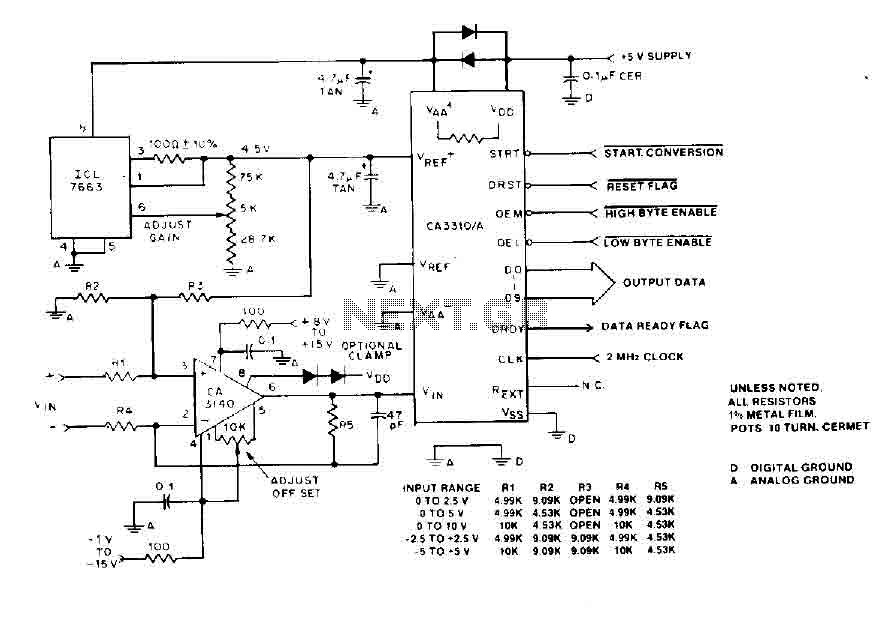
The BiMOS CA3140 operational amplifier offers excellent orientation capabilities for high bandwidth signal inputs and can swiftly adjust the energy output at its terminal CA33IO WINE. The CA3140 can also operate close to the negative supply rail. If the...
Instructions for supervising landscaping projects recommended by satellite relay protection and automatic safety devices. This includes information on the general table for three remote programs related to petrochemical engineering construction, electrical transmission, and the intelligent implementation of community weak...
This two-transistor AM radio circuit is also referred to as a "mini-radio." It utilizes only two transistors and a few passive components, which makes it very easy to construct. The two-transistor AM radio circuit operates by utilizing a simple design...
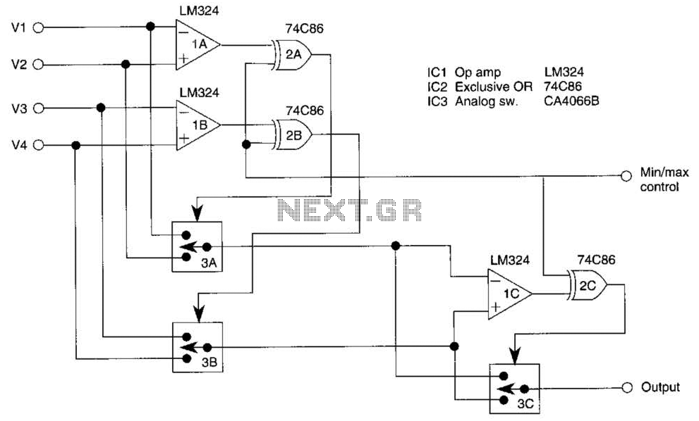
This circuit outputs the maximum or minimum of four input voltages, V1, V2, V3, and V4. Each of these input voltages ranges from 0 to 5 V. The output of the circuit is the maximum of V1, V2, V3,...
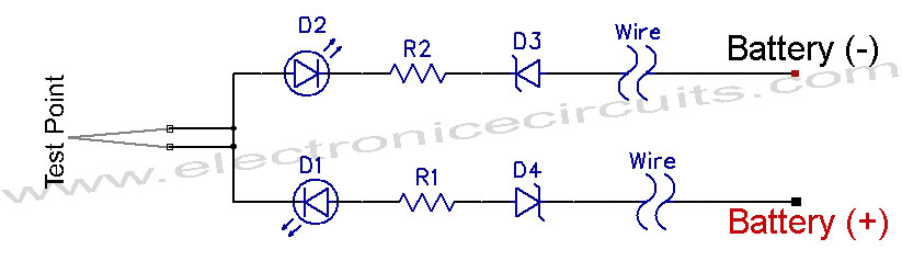
12V Vehicle Electrical Wiring Tester Circuit. This tester is useful for checking vehicle electrical circuits. Two LEDs indicate whether the circuit is live or not. The 12V vehicle electrical wiring tester circuit is designed to provide a simple yet effective...