
Crystal Oscillator counter
The circuit described utilizes a crystal oscillator to produce a stable frequency, which is essential for accurate timing applications. The choice of a 50 kHz crystal allows for a division to 1 second using a binary counter configuration. The CD4040 counters are employed in a cascaded arrangement to achieve the required division ratio. Specifically, the binary count of 50,000 is reached by combining the outputs of specific bits from the counters, namely bits 15, 14, 9, 8, 6, and 4.
When transitioning to a 100 kHz crystal, the counting scheme shifts, necessitating a rightward movement of the bits in the binary representation to accommodate the increased frequency. This results in a new total of 100,000, derived from the sum of bits 16, 15, 10, 9, 7, and 5.
For a 1 MHz crystal, the required resistor values in the oscillator circuit must be adjusted to maintain stability and proper operation. The original 330 kΩ resistor is significantly reduced to approximately 15 kΩ to accommodate the higher frequency. The output from the counters is managed by a Schmitt Trigger inverter, which generates a reset pulse upon reaching the terminal count. This pulse is critical for resetting the counters to zero, ensuring that timing remains accurate.
The timing inaccuracies introduced by the reset pulse width, although minimal, must be acknowledged, especially at higher frequencies where the pulse width approaches the clock cycle duration. The 4040 CMOS counters require a minimum reset pulse width of around 1.5 µs, which places constraints on the design and operation of the circuit. This careful consideration of component values and configurations is essential for achieving the desired accuracy in timing applications.Using a 50 Khz crystal, a count of 50000 is detected when the appropriate counter bits that add up to 50000 are all high. This corresponds to bits 15 (32768) + 14 (16384) + 9 (512) + 8 (256) + 6 (64) + 4 (16). Bits 14 and 15 are the 3rd and 4th stages of the second counter, bit 0 is the first stage of the first counter (Q1, pin 9).
To use a 100 Khz crystal, each bit would be moved one to the right so the total would be (65536 + 32768 + 1024 + 512 + 128 + 32 = 100,000). Using a 1 Mhz crystal, the following bits would be needed: The schematic below illustrates dividing a crystal oscillator signal by the crystal frequency to obtain an accurate (0.01%) 1 second time base. Two cascaded 12 stage counters (CD4040) form a 24 stage binary counter and the appropriate bits are gated together to produce the desired division.
Using a crystal of some even multiple of 2 is desirable so that one stage of the counter automatically toggles every second which eliminates the need for the NAND gate and reset circuitry, however the circuit below illustrates using a crystal which is not an even multiple of 2 and so requires additional components. At 1 Mhz, the 330K resistor in the oscillator circuit will need to be reduced proportionally to about 15K.
When the terminal count is reached, a 7 uS reset pulse is generated by the Schmitt Trigger inverter stage that follows the NAND gate. The 47K resistor and 470 picofarad capacitor sustain the output so that the counters are reliably reset to zero.
This is less than one clock cycle at 50Khz and does not introduce an error but would amount to 7 cycles at 1 MHz which would cause the counters to lose 7 microseconds of time per second. It's not much of an error (7 parts in a million) but it would be there. The minimum reset pulse width for the 4040 CMOS counters is about 1.5 uS, so the reset pulse cannot be made much shorter.
🔗 External reference
Related Circuits
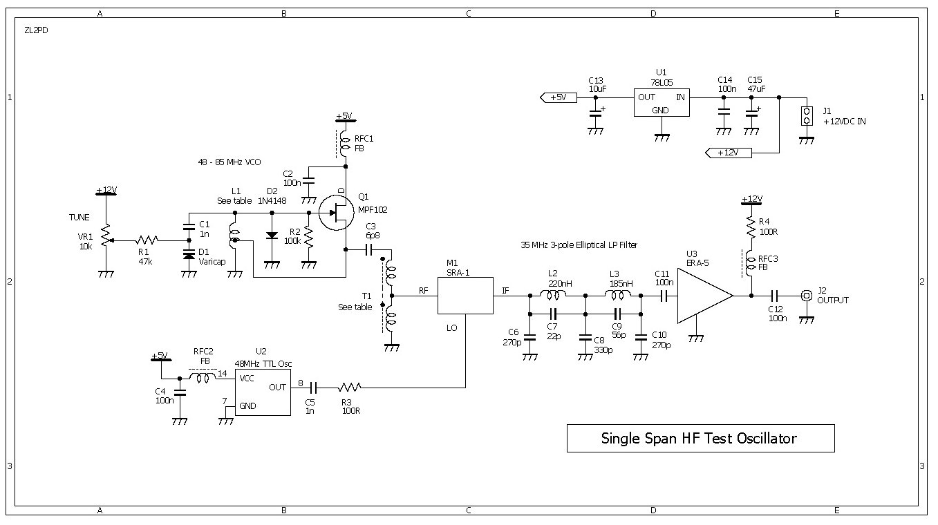
This compact RF oscillator operates across the entire frequency range of 0.4 to 30 MHz in a single sweep of the dial, featuring a terminated 50-ohm output of more than 300 mV throughout the HF band. Unlike most signal...
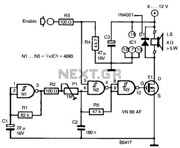
A CD4093 chip and several components form a siren oscillator that drives power MOSFET Tl. A speaker is directly powered by this device. The siren is activated by a logic high signal applied to the ENABLE input. The circuit comprises...
Astable or free-running multivibrators have been used in home-built amateur radio equipment for many years. The basic circuit is a two-stage amplifier with AC-coupled feedback from output to input. One transistor stage is on (conducting current) while the other...
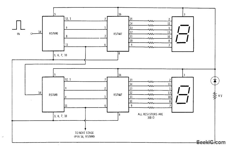
A simple interconnection of the RS7490 decade counter, RS7447 decoder, and a 7-segment digital display for each desired digit creates an ideal counter for classroom demonstrations and science fair exhibits. With the addition of two extra stages, the display...
Transistor Q1, a 2N3563, and its associated components form an oscillator circuit that will oscillate if, and only if, a good crystal is connected to the test clips. The output from the oscillator is then rectified by the 1N4148...
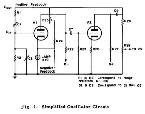
After repairing several Hewlett Packard vacuum tube voltmeters, research was conducted on the company's history. An HP-200C oscillator was located, which closely resembles the company's initial product. It is a Wien bridge resistance-tuned oscillator featuring a light bulb stabilized...