
Morse Code astable Oscillator

Tracing the circuit from left to right first brings us to the multivibrator circuit which is composed of Q1 and Q2. The oscillation frequency of the multivibrator is approximately 700 hertz and is set by the RC network formed by the 100K resistor and the 0.01 µF capacitor connected to each transistor base terminal. The approximate time off for each transistor is given by the formula:
[ Time Off = 0.7 * R * C ] with R in ohms and C in farads.
It may be more practical to leave the resistance value fixed and vary the capacitor value to obtain a desired oscillation frequency. Rearranging the above formula allows this:
[ Total Time Off = 1 / Frequency ] with Total Time Off being the total number of seconds that both transistors are off and Frequency in hertz.
Once the total time off is known, it must be divided by 2 as each transistor is off half of the total time off in this symmetrical circuit. Then the capacitor value can be solved as follows:
[ Time Half = Total Time Off / 2 ]
[ Capacitor = Time Half / ( 0.7 * R )] with Capacitor answer in farads.
For the given schematic:
- R = 100K, desired frequency = 700 hertz.
- Total Time Off = 1 / F → 1 / 700 = 0.00143 seconds.
- Time Half = Total Time Off / 2 → 0.00143 / 2 = 0.00071 seconds.
- Capacitor = Time Half / ( 0.7 * R ) → 0.00071 / ( 0.7 * 100000 ) = 0.0000001 farads = 0.01 microfarads.
For 600 hertz, the capacitors would be 0.012 µF, and for 400 hertz, 0.018 µF.
It may be necessary to adjust the base resistor value to achieve a specific oscillation frequency. The rule of thumb is that the base resistor should be approximately ten times the value of the collector resistor, assuming the base-bias resistor is connected to VCC as shown.
The output of the multivibrator is buffered by the high input impedance of an emitter follower (Q3). This configuration prevents the oscillation frequency from changing when the output load is altered. The audio frequency (AF) stage connected to the emitter-follower is a standard high-gain common-emitter amplifier that has been utilized in many projects. As the multivibrator is buffered by two amplifier stages, good frequency stability is achieved, and frequency variations are negligible when adjusting the volume control potentiometer. The final stage is a common-collector amplifier capable of driving low impedance headphones with reasonable volume. This design ensures that the user can experience consistent performance, making it suitable for applications like Morse code practice oscillators and electronic keyers.Astable or free-running multivibrators have been used in home-built amateur radio equipment for many years. The basic circuit is a two stage amplifier with AC-coupled feedback from output to input. One transistor stage is on ( conducting current ) while the other is off ( not conducting current ) until the stages switch conducting states repeatedly at a specific frequency.
The oscillation frequency is set by the resistor and capacitor values connected to the base terminal of each stage. This RC network determines how long the transistor stays in the off position. Presented are two projects which utilize astable multivibrators built using the ubiquitous 2N3904 BJT.
The first project is a code practice audio-frequency oscillator while the second is a simple , no-frills electronic keyer for keying a transmitter. Either circuit would be a great first project to learn how to build circuits using Ugly Construction.
Above is the schematic for a simple Morse code practice oscillator. This circuit was originally built with 2N3904 transistors, however many different NPN transistors could be substituted as required. Tracing the circuit from left to right first brings us to the multivibrator circuit which is composed of Q1 and Q2.
The oscillation frequency of the multivibrator is ~ 700 hertz and is set by the RC network formed by the 100K resistor and the 0.01 uF capacitor connected to each transistor base terminal. The approximate time off for each transistor is given by the following formula: [ Time 0ff = 0.7 * R * C ] with R in ohms and C in farads.
It maybe more practical to leave the resistance value fixed and vary the capacitor value to obtain a desired oscillation frequency. Rearranging the above formula allows this : [ Total Time Off = 1 / Frequency ] with Total Time Off being the total number of seconds that both transistors are off and Frequency is in hertz.
Once the total time off is known, you must divide that answer by 2 as each transistor is off half of the total time off in this symmetrical circuit. Then you simply solve for the capacitor value: [ Time Half = Total Time Off / 2 ] [ Capacitor = Time Half / ( 0.7 * R )] with Capacitor answer in farads.
Lets run the numbers to solve for the capacitor values in the schematic; R = 100K, desired frequency = 700 hertz. Total Time Off = 1 / F ----> 1 / 700 = 0.00143 seconds. Time Half = Total Time Off / 2 ----> 0.00143 / 2 = 0.00071 seconds. Capacitor = Time Half / ( 0.7 * R ) ----> 0.00071 / ( 0.7 * 100000 ) = 0.0000001 farads = 0.01 microfarads.
For 600 hertz, the capacitors would be 0.012 uF and for 400 hertz, 0.018 uF. As you can see it is maybe necessary to adjust the base resistor value to achieve a specific oscillation frequency. The rule of thumb is that the base resistor should be ~ten times the value of the collector resistor assuming the base-bias resistor is connected to VCC as shown.
The output of the multivibrator is buffered by the high input impedance of an emitter follower Q3. This serves to prevent the oscillation frequency from changing when the output load is changed. The AF stage connected to the emitter-follower is a standard high gain common-emitter amp that has been used in many of the projects on this web site. As the multivibrator is buffered by 2 amplifier stages, good frequency stability is realized and frequency changes are negligible when turning the volume control pot.
The final stage is a common-collector amplifier which can drive low impedance headphones with reasonable volume. 🔗 External reference
Related Circuits
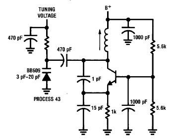
Inquiries about selecting the L, C, and R values to achieve a desired frequency are common. It is essential to understand the relationship between these components and the frequency they produce. The desired frequency can be calculated using the...
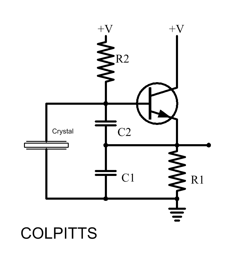
A simple high-efficiency Colpitts oscillator is utilized in higher frequency ranges, specifically above 50 MHz. Colpitts oscillators are preferred as stray circuit capacitance is in parallel with the desired feedback capacitance, preventing undesirable spurious resonances that may occur with...
The current meter has a measurement range from 100 pA to 3 mA full scale. The voltage across the input is 100 µV at the lower ranges, increasing to 3 mV at 3 mA. Buffers on the operational amplifier...
BFO is a simple device which helps us to listen SSB and CW transmissions. Reception of SSB and CW signals requires a product detector or BFO (Beat Frequency Oscillator) to reinsert the missing carrier. This circuit is very simple...
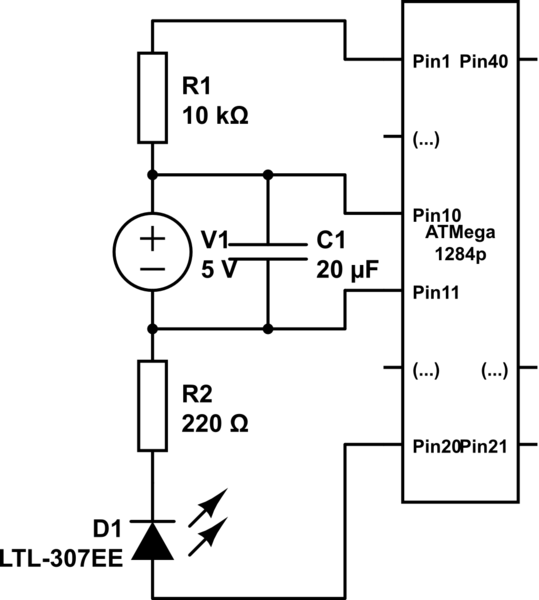
Program an ATmega1284P using an AVR Dragon and the Arduino IDE. The mighty1284p library has been installed, and after writing the sketch, it is compiled using the Arduino IDE. The compilation process creates a hex file in a temporary...
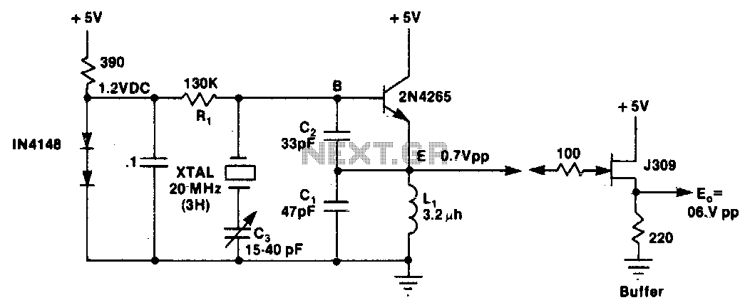
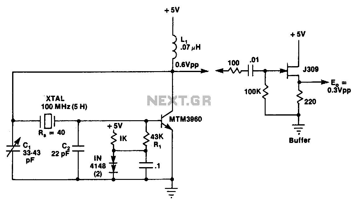
L1 and C1 are selected to resonate at a frequency below the desired crystal harmonic but above the crystal's next lower odd harmonic. Capacitor C2 should have a value between 30-70 pF, independent of the oscillation frequency. There is...