
Crystal oscillator simulation
The circuit in question is designed to function as a crystal oscillator within a GPSDO setup. The primary components include a crystal resonator, an amplifier, and associated passive components such as capacitors and resistors. The oscillator operates by generating a stable frequency signal, which is critical for maintaining accurate timing in GPS applications.
CircuitLab, as a simulation tool, proves invaluable for visualizing circuit behavior without the need for physical assembly. Users can design circuits by placing components on a virtual workspace, connecting them with wires, and running simulations to observe voltage and current waveforms. The ease of use allows for rapid iterations and modifications, which is particularly beneficial in troubleshooting and optimizing circuit performance.
In the initial testing phase, the circuit was analyzed without loading, which provided a baseline for expected performance. However, when the oscilloscope was introduced, its inherent loading effect altered the output characteristics. The oscilloscope's probe, particularly in its 1x setting, presented a lower impedance load, which can significantly affect the resonator's ability to oscillate at its intended amplitude. This phenomenon is a common consideration in high-frequency circuit design, where loading effects can lead to discrepancies between theoretical and practical measurements.
To mitigate the loading effect, the oscilloscope probe was switched to a 10x setting, which increases the impedance and reduces the loading on the circuit. This adjustment is a standard technique in electronic measurements, allowing for more accurate readings by minimizing the influence of measurement equipment on the circuit under test.
Figures referenced in the original description serve to illustrate the various stages of simulation and measurement, providing a visual representation of the circuit's performance. The output waveforms captured on the oscilloscope can be analyzed to assess the oscillator's frequency stability, amplitude, and overall functionality, ensuring that it meets the specifications required for GPS disciplined applications.Originally I was going to call this posting "Crystal Oscillator Blues". This is given because things have not been going well with constructing the crystal oscillator for the GPS Disciplined Oscillator, as outlined in my last posting ( GPSDO - Crystal Oscillator ). However, a couple of things have gone quite well, interestingly well as it happens. There are some interesting points in here, and I actually do think the oscillator is operating just fine, based on the observations made. So where to start. First interesting point is CircuitLab -. I wanted to determine what the circuit should be doing in theory. So I started to look up a suitable SPICE application and came across CircuitLab. The best way to describe this application is like comparing a standalone email program, say Microsoft Outlook or Mozilla Thunderbird, to Google Mail.
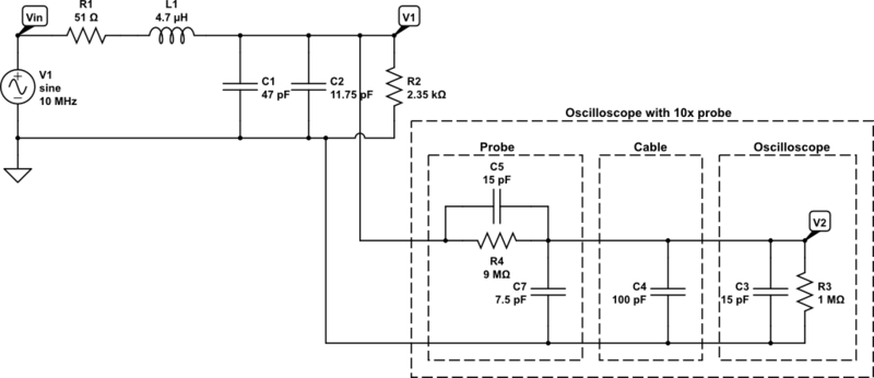
It`s all online - interesting. But what`s more impressive is just how user friendly it is. Within 2 minutes I was designing the resonator circuit and then testing it. Unbelievable! Figure 1 shows what it looks like, using the resonator circuit of the oscillator as an example. So exactly what should the oscillator with amplifier board (resonator) actually be doing Good question! This is where a circuit simulator such as CircuitLab is useful. Figure 2 shows the schematic for the circuit and Figure 3 shows the output at the measurement points indicated.
All good so far, but this is certainly not what I saw when making measurements with an actual OCXO and amplifier board. First I made measurements with an unloaded system - per the circuit above minus the 10 pF capacitor (representing the connecting cable) and the 2.
2 kOhm load resistor. Figure 4 shows the simulated circuit, Figure 5 shows the simulated output and Figure 6 shows a capture of my oscilloscope display. Using the voltage naming in Figure 4, the oscilloscope shows Vin being 2. 8 Vpp and V1 being 1. 4 Vpp: V1 is not really the ~5 Vpp expected! So where are things going wrong The loading of the resonator circuit would certainly alter the ouptut amplitude a little - compare Figures 3 and 5.
But still something is not quite right. "Loading" is of course the operative word here - the oscilloscope with its probe will provide a load of it`s own. So quickly creating a model for the oscilloscope and 1x probe [1] in the CircuitLab simulator yielded the results shown in Figures 7 and 8.
Vin is still 2. 8 Vpp, but V1 is 1. 2-1. 3 Vpp! Thus the oscilloscope appears to be loading the resonator and it can`t produce what we want. To test out this theory further, I switched the oscilloscope probe to its 10x setting (and also re-did the simulation). Changing this setting does a couple of things, including providing a much higher impedance load, useful for the purpose of this testing.
Figure 9 and 10 are the new simulated circuit with output, and Figure 11 is a capture of the oscilloscope. 🔗 External reference
Related Circuits
This circuit is a crystal oscillator that operates at a frequency of 3.5 MHz. The crystal oscillator circuit utilizes a quartz crystal resonator to generate a stable frequency output. The primary components typically include the crystal, an amplifier (often a...

A PLL (Phase-Locked Loop) oscillator is utilized to achieve a very stable frequency with minimal distortion in the sine wave output. Its stability is comparable to that of crystal-based oscillators, while the distortion level of the sine wave output...

Although analog and digital controllers may seem vastly different, their principles of operation are often quite similar. Therefore, popular analog tools like Spice can still be utilized to enhance common digital proportional-integral controllers through analysis, without the need for...

A variable Wien bridge provides frequency tuning from 20 Hz to 20 kHz. Gain control comes from the positive temperature coefficient of the lamp. When power is applied, the lamp has a low resistance value, resulting in high gain...
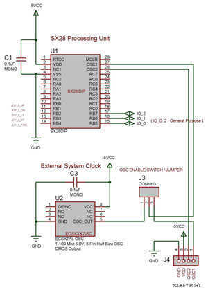
The SX 28 internal oscillator is not that fast, so an external oscillator can be hooked up to the processor as shown in the diagram to increase the operation cycles per second. The SX 28 microcontroller is designed with an...

This circuit operates effectively across a broad frequency spectrum. XTAL 1 serves as a fundamental-frequency crystal. Tl and CI are adjusted to match the input frequency. This circuit can be utilized as a straightforward shortwave converter for AM radios,...
Warning: include(partials/cookie-banner.php): Failed to open stream: Permission denied in /var/www/html/nextgr/view-circuit.php on line 713
Warning: include(): Failed opening 'partials/cookie-banner.php' for inclusion (include_path='.:/usr/share/php') in /var/www/html/nextgr/view-circuit.php on line 713