
PLL Oscillator for Medium Wave Application

The PLL oscillator circuit operates by leveraging the principles of feedback and phase comparison to maintain a stable output frequency. The core components include the VCO, phase detector, loop filter, and frequency divider. The VCO generates an oscillating signal, the frequency of which is influenced by the control voltage. The phase detector compares the phase of the VCO output with that of the reference clock, producing an error signal that reflects the phase difference between the two signals. This error signal is then filtered by the loop filter to produce a smooth control voltage, which adjusts the capacitance of the varactor in the VCO, thereby fine-tuning its frequency.
The integration of a frequency divider allows for output frequencies that exceed the reference frequency, effectively multiplying the reference frequency by a predetermined factor. This is particularly beneficial in applications requiring higher frequencies than the reference clock can provide. The MC145106 IC serves as the primary control unit for the PLL, facilitating the necessary adjustments to maintain frequency stability and low distortion.
The design considerations for the PLL oscillator include ensuring that the power supply is stable and well-decoupled to prevent noise from affecting the oscillator's performance. Additionally, the selection of the varactor and other components should be made based on the desired frequency range and application requirements. Proper layout and grounding techniques are essential to minimize interference and enhance the overall performance of the PLL oscillator circuit.PLL oscillator is used to get very stable frequency woth very low distortion of sine wave output. The stability is equal to crystal-based oscillator, and the low distortion level of the sine wave output is equal to LC based oscillator. The method ofPLL control inPLL oscillatois done by adjusting the frequency of sine wave VCO (voltage controlled o
scillaltor). The VCO is an LC based oscillator, but the capacitor is not a fixed one, but it`s a varactor, a variable capacitor which its capacitance value is variable depends on the applied voltage. The control of this voltage change the frequency of the VCO. This voltage control is coming from a phase difference detector that detect the phase difference between the crystal reference clock and the VCO output.
If the frequency of the VCO output is different then the error signal from the phase difference detector will try to correct the VCO until the VCO has the same frequency and the phase difference is slipped at certain level to produce the voltage control that maintain the VCO frequency. To get the frequency higher than thePLL oscillator`s internal reference clock, we just need to insert a frequency divider between the VCO and the phase difference detector.
Using this method, now the PLL control system will maintain the divided VCO output frequency to be same with the reference, so thePLL Oscillatorthat come directly from the VCO has the frequency of the reference frequency multiplied by the division value of the programmed divider. SimplePLL oscillatorcircuit can be constructed using MC145106 IC, and it need only external VCO to produce a sine wave output.
The crystal frequency is 4608 kHz for European medium wave frequency spacing standart, and 5120 for USA. The power supply must be regulated and well decoupled. 🔗 External reference
Related Circuits
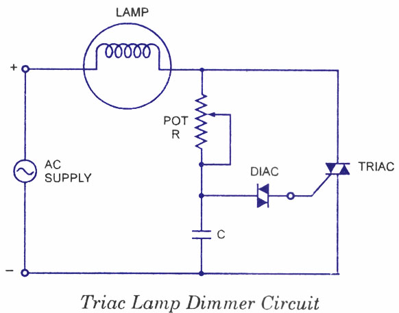
Diacs are widely used as triggering devices in triac phase control circuits due to their symmetrical bidirectional switching characteristics. These circuits are employed in applications such as lamp dimmers, heat control, and universal motor speed control. While a triac...
The operational amplifier Wien-bridge oscillator offers insight into classic oscillator design through feedback analysis. Feedback analysis determines whether a circuit is stable or unstable. In amplifier design, particularly for high-speed applications, avoiding conditions that lead to oscillation is crucial....
In linear equipment design, it is sometimes necessary to take a voltage that is referenced to a certain DC level and generate an amplified output that is also referenced. In linear circuit design, the process of amplifying a voltage that...
This oscillator is a variation of the oscillator presented by Ulrich L. Rohde, DJ2LR, in his article "Evaluating Noise Sideband Performance in Oscillators," published in Ham Radio, October 1978, Page 51. The original circuit can be found at the...
Silicon controlled rectifiers (SCR) can easily oscillate if there is an inductor (a speaker coil in this case) which gives just enough extra voltage to completely switch off the sustain current. In this way a new cycle may start...

This oscillator circuit is designed to generate both a rectangular wave and a triangle waveform, operating within the frequency range of 1 kHz to 10 kHz. The first operational amplifier in the configuration produces the square wave, while the...