
Crystal Oscillator Design
The crystal oscillator circuit utilizes a quartz crystal resonator to generate a stable frequency output. The primary components typically include the crystal, an amplifier (often a transistor or operational amplifier), and feedback components such as resistors and capacitors. In this specific circuit, the 3.5 MHz crystal serves as the frequency-determining element, ensuring that the oscillator maintains a consistent output frequency with minimal drift.
The circuit configuration can vary, but a common design involves the crystal connected in a feedback loop with an amplifier. The amplifier boosts the signal generated by the crystal, while the feedback network ensures that the output remains in phase with the input, thus sustaining oscillation. The stability of the output frequency is primarily influenced by the characteristics of the crystal, including its cut, temperature stability, and load capacitance.
In practical applications, crystal oscillators are widely used in clocks, timers, and frequency synthesis, where precise timing is crucial. The output waveform is typically a square wave, which may require further conditioning, such as filtering or shaping, depending on the intended application. Proper layout and component selection are essential to minimize noise and ensure reliable operation at the specified frequency.HI, i Just wanted to understand this circuit better and discuss with people So here it is a ,crystal oscillator It uses a 3.5Mhz Crystal and.. 🔗 External reference
Related Circuits
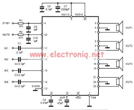
The input capacitor is used for low-frequency cut-off, with a standard value of 0.1 µF, resulting in a cut-off frequency of approximately 16 Hz. The input capacitor plays a crucial role in filtering unwanted low-frequency signals in electronic circuits. By...
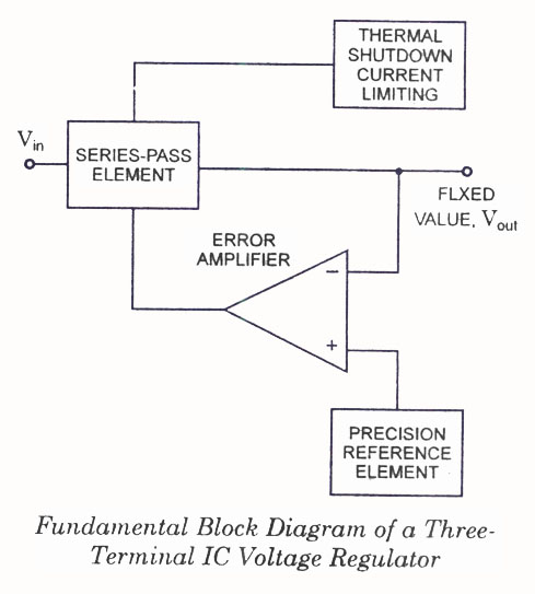
IC Voltage Regulators - Circuit diagram and block diagram of linear, fixed, adjustable (positive and negative), and switching voltage regulators. IC voltage regulators are essential components in electronic circuits, providing stable output voltages from a varying input voltage source. They...
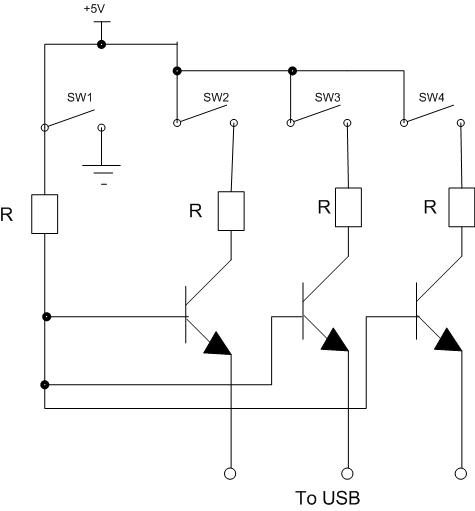
Four switches will be connected to a USB joystick board. The USB board has +5V and ground connections and emulates a button press. The circuit involves interfacing four mechanical switches with a USB joystick interface. The USB joystick board typically...
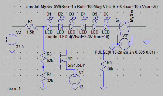
A suitable method to sense when some LEDs in a garage door opener are illuminated. A power source, potentially the same as Vout, connects to a 1.5 kΩ resistor, which then connects to six LEDs followed by a transistor....

Design a Colpitts oscillator in a common collector configuration using a single BJT. Provide base current to ensure the transistor operates correctly, which can be achieved using a potential divider (between Vcc and ground). It is advisable to use...
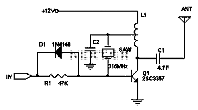
The circuit principle involves the use of an LC oscillator, which typically experiences significant frequency drift. Surface Acoustic Wave (SAW) devices have emerged as a solution to this issue, offering frequency stability comparable to that of crystal oscillators. SAW...