
Crystal Radio Antenna Preamplifier
The project involves the conversion of a Tesla coil into a functional crystal radio set, primarily aimed at educational demonstrations. The primary challenge encountered is the inadequate size of the antenna, which is crucial for capturing radio signals effectively. The theoretical requirement for a quarter-wavelength antenna, which ranges from 100 to 500 feet, presents a significant barrier in urban environments, where space is limited. To address this, a compact 60-square-foot wire antenna has been implemented, yielding moderate reception quality.
To enhance the signal reception, the integration of a pre-amplifier circuit is proposed. A schematic derived from the Antique Radio Forums has been identified as suitable for a smaller 10-square-foot antenna, demonstrating effective performance in similar applications. There is consideration for adding an extra amplification stage using a second transistor, which raises concerns about potential noise amplification. As a solution, the installation of an audio amplifier after the tuning coil has been suggested, which may provide a cleaner output.
An update on the project reveals a productive discussion on optimizing the circuit design. The recommendation to substitute the original transistor with a 2N5179 while adding a class B complementary emitter follower on the output has been highlighted as a promising approach. This modification aims to improve the overall amplification quality while managing noise levels. The efficacy of using a 2N3904 as a simple RF amplifier has been recognized, particularly in contrast to the MPF102, which necessitates a fixed choke for improved AM reception. The anticipation of testing this new configuration is noted, with expectations of enhanced AM and long-wave reception performance.Adapting one of my failed Tesla coils into a crystal radio set to show the neighborhood kids. I`ve run into the #1 problem everyone faces not enough antenna to generate a strong signal. I read somewhere that a proper AM antenna should be between 100 500 ft for good reception (technically known as quarter wavelength). I don`t think anyone living in a city can install an antenna of that size. So I managed to push about 60 ² of wire into the air, and I was getting OK results from it but thinking that maybe a simple pre-amplifier circuit would be a good thing to squeeze a bit more performance. So I found this schematic from the Antique Radio Forums. This was designed for a 10 ² antenna and does work quite well. I`m thinking about adding an extra stage of amplification through another transistor does anyone know if this is a good or bad thing Obviously I will be amplifying the noise too, so maybe an audio amplifier would be better, installed after the tuning coil.
UPDATE : Since posting yesterday, this article has generated quite a bit conversation behind the scenes one thing that has come up is that replacing the transistor with a 2N5179 and then adding a class B complementary emitter follower on the output would be a good strategy. I`ll be working on this and posting a follow up to show what happens. I am very impressed you took a simple transistor such as the 2N3904 and made a RF amplifer. I have been using the other transistor called the MPF102 to make a preamplifer, but this one you made does not require a fixed choke like the other circuit I have built to improve AM reception.
I cannot wait to try this one out for to improve AM and long wave reception. Thanks! 🔗 External reference
Related Circuits
Ham Radio (amateur radio) is a popular hobby amongst electronics enthusiasts all over the world. Basically the hobby involves a person in making his own gear consisting of a receiver and transmitter or a transceiver (a receiver and a...
Since the volume control is after the gain stage, the preamp can be easily overloaded. I tried to limit the input signal by mounting a 470 k resistor in series with the CD input. A voltage divider is formed...

Another frequency-determining device is the crystal. The crystal may be used with a tank circuit, or it may function independently. Crystals exhibit a characteristic known as the piezoelectric effect, which is the property of a crystal that allows mechanical...
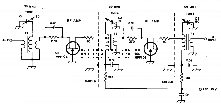
C1, C2, and C3 are miniature ceramic or plastic trimmers. T1 (main winding) has an inductance of 0.34 µH, utilizing 11 turns of No. 24 enameled wire wound on a T37-10 toroid core. The antenna winding consists of one...
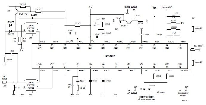
The integrated circuit (IC) is a multistandard vision and sound intermediate frequency (IF) phase-locked loop (PLL) demodulator that operates without the need for alignment. It supports multiple standards, including PAL, SECAM, and NTSC, and is capable of processing both...
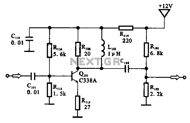
The amplifier circuit is designed as a pre-amplifier configuration. It utilizes transistor Q101 and other components such as inductor L101 and biasing elements. The transistor operates as a common emitter intermediate frequency (IF) amplifier. The IF signal is coupled...