
Crystals

The crystal oscillator is a critical component in various electronic applications, providing precise frequency control essential for timing and synchronization in circuits. The operation of a crystal oscillator relies on the piezoelectric properties of the quartz crystal, which allows it to convert electrical energy into mechanical vibrations and vice versa. The natural resonant frequency is determined by the physical dimensions and the cut of the crystal, which can be optimized for specific applications.
In practical implementations, the crystal is often part of a feedback loop in an oscillator circuit, where it ensures stable oscillation frequencies. The equivalent circuit model of the crystal includes series and parallel resonant frequencies, which are crucial for understanding its behavior in different circuit configurations. The high Q factor indicates a narrow bandwidth around the resonant frequency, contributing to the oscillator's ability to maintain frequency stability over temperature variations and aging.
The design of the holder for the crystal is also significant, as it must not only support the crystal physically but also allow for its mechanical vibrations without introducing damping that could affect performance. The choice of materials for the holder and the method of mounting the crystal can influence the overall performance of the oscillator.
In summary, quartz crystals are indispensable in modern electronics, enabling precise frequency generation and control through their unique piezoelectric properties and high Q factors. Their application extends to various fields, including telecommunications, computing, and signal processing, where accurate timing is paramount.Another frequency-determining device is the CRYSTAL. The crystal may be used with a tank circuit, or it may perform alone. Crystals exhibit a characteristic known as the PIEZOELECTRIC EFFECT. The piezoelectric effect is the property of a crystal by which mechanical forces produce electrical charges and, conversely, electrical charges produce mecha nical forces. This effect is a form of oscillation similar to the flywheel effect of a tank circuit. The piezoelectric effect can be seen in a number of crystal substances. The most important of these are the minerals quartz and Rochelle salt. Although quartz does not exhibit the piezoelectric effect to the degree that Rochelle salt does, quartz is used for frequency control in oscillators because of its greater mechanical strength. Another mineral, tourmaline, is physically strong like quartz; but because it is more expensive, it is not used extensively as an fdd.
This discussion will deal only with the quartz crystal. The crystals used in oscillator circuits are thin sheets, or wafers, cut from natural or synthetic quartz and ground to a specific thickness to obtain the desired resonant frequency. The crystals are mounted in holders, which support them physically and provide electrodes by which voltage is applied.
The holder must allow the crystals freedom for vibration. There are many different types of holders. One type is shown in the figure below. The frequency for which a crystal is ground is referred to as the NATURAL RESONANT FREQUENCY of the crystal. Voltage applied to the crystal produces mechanical vibrations which, in turn, produce an output voltage at the natural resonant frequency of the crystal.
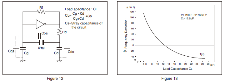
A vibrating crystal can be represented by an equivalent electrical circuit composed of capacitance, inductance, and resistance. The figure below, view (A), illustrates the symbol of a crystal; view (B) shows an equivalent circuit for the crystal.
View (C) shows an equivalent circuit for the crystal and the holder; C1 represents the capacitance between the metal plates of the holder The Q (discussed in the tutorials on "Tuned Circuits") of a crystal is many times greater than that of an LC tank circuit. The high Q is present because the resistance in the crystal is extremely small. Commercially produced crystals range in Q from 5, 000 to 30, 000. The high Q causes the frequency stability to be much greater than that of an ordinary LC tank circuit.
This is the reason a crystal is used in many sine-wave generator circuits. As you have just studied, a basic oscillator can be broken down into three main sections: a frequency-determining device, an amplifier, and a feedback circuit. The frequency-determining device in an LC oscillator is usually an LC tank circuit. Although the tank circuit is normally found in the input circuit of an oscillator (both electron tube and transistor), it sometimes appears in the output circuit.
The differences in magnitude of plate and collector currents and shunting impedances are considerations in the designed locations of such tank circuits. In both solid-state and electron tube circuits, oscillations take place in the tuned circuit. Both the electron tube and the transistor function primarily as electrical valves that amplify and automatically deliver to the input circuit the proper amount of energy to sustain oscillations.
In both tube and transistor oscillators, the feedback circuit couples energy of the proper amount and of the correct phase from the output to the input circuit to sustain oscillations. The previous tutorials on "Tuned Circuits". described the resonant or tank circuit and how a sinusoidal signal is generated by the action of an inductor and a capacitor.
The feedback signal is coupled from this circuit by either of two means. The first method is to take some of the energy from the inductor. This can be done by any one of the three ways shown in the figure below, views 🔗 External reference
Related Circuits
The drive level of a crystal unit is indicated by the operating power level or current consumption. Operating the crystal unit at excessive power levels can degrade its characteristics, potentially causing frequency instability or physical failure of the crystal...
This article explains the specifications and characteristics of crystals and crystal oscillators, and aids in specifying crystals and working with crystal vendors. The article covers the significant performance characteristics of crystals, which include resonance frequency, resonance mode, load capacitance,...
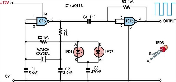
This circuit was designed to enable the use of watch crystals in an existing CMOS oscillator circuit powered by a 12V supply. The challenge arises because these crystals typically operate at a maximum supply voltage of approximately 6V; exceeding...
Electronics tutorial about quartz crystal oscillators, including harmonic, overtone, Pierce oscillator, and crystal quartz oscillator circuits. Quartz crystal oscillators are vital components in modern electronics, providing stable frequency references for a variety of applications. They utilize the piezoelectric properties of...
.jpg)
Integrated circuits (ICs) with on-board oscillators that require low-frequency fundamental crystals are common; however, IC frequency multipliers now require the higher frequencies provided by third overtone crystals. The third-overtone (3OT) crystal oscillator is more complex than its fundamental counterpart,...
Because it uses few parts, a printed circuit board is not necessary; components can simply be soldered to one another. However, a box is desirable for operating convenience. The case and aerial from a discarded toy walkie-talkie was used...