
Crystal Radio Circuits
The crystal radio circuit operates by utilizing a resonant LC circuit formed by the inductor and capacitor, allowing it to tune into specific radio frequencies. The inductor is constructed with a specific number of turns, which can be adjusted based on the desired frequency range. The capacitor is adjustable, enabling fine-tuning of the circuit to select different stations. The diode rectifies the radio frequency signals, converting them into audio frequencies that can be heard through the earphone.
To enhance performance, the design may include additional components such as a variable resistor or potentiometer to adjust the sensitivity of the diode. The ground connection is crucial for optimal operation; it should be as low-resistance as possible to minimize noise and improve signal clarity.
Antenna design can vary, with options including long wire antennas or loop antennas, each offering different performance characteristics based on the environment and available space. Proper grounding techniques and protection against electrical surges, such as lightning arrestors, are essential to safeguard the circuit and ensure longevity.
In summary, the crystal radio circuit is a simple yet effective design that requires careful attention to component selection, connections, and environmental factors to achieve optimal performance. Proper experimentation and adjustments can lead to a successful and enjoyable radio experience.The crystal radio gets its name from the galena crystal (lead sulfide) used to rectify the signals. A "cat`s whisker" wire contact was moved about the surface of the crystal until a diode junction was formed. The 1N34A germanium diode is the modern substitute for galena and most other germanium small-signal diodes will also work well.
Silicon diod es are not a good choice because their much higher barrier potential requires larger signals for efficient rectification. Certain silicon Schottky diodes with low barrier potential will work well but most small-signal Schottky diodes will not perform as well as a garden-variety germanium diode.
The circuit is quite simple but many pitfalls await the novice. The first precaution is most important! The crystal radio works best with a long, high outdoor antenna but the beginner may not fully appreciate the danger of bringing such a wire into the house. Lightning strikes to the antenna will probably destroy the crystal radio but if precautions are not taken, much more damage will result.
The best strategy is to incorporate a commercial lightning arrestor with a straight, heavy gauge ground wire leading down to a buried water pipe. It is not sufficient to disconnect the antenna from the receiver during thunderstorms. Other pitfalls are less dangerous and relate to the receiver`s performance. A common mistake when building a crystal radio is to load the tuned circuit excessively. The Q of the tuned circuit must remain high to give selectivity or strong radio stations will all mix together.
A good design will usually have low-impedance taps on the inductor for connections to the antenna and diode as shown in the schematic. A long wire antenna with a good ground connection will connect to the lowest impedance tap whereas a shorter antenna with no ground connection may connect to a higher tap.
The diode may be experimentally moved to different taps and even across the whole coil for maximum sensitivity. The antenna and diode connection may be made with alligator clips for easy experimentation. Another potential problem area is the earphone. Not all crystal earphones are sensitive and the experimenter should test a few to get a "good" one. High impedance dynamic earphones are a bit more reliable and can give excellent results. Try an old telephone receiver or a modern portable tape player headset (some are high-Z and fairly sensitive).
Low impedance earphones like those used with many portable radios will not work at all. A simple test is to hold one earphone wire between the fingers while scraping the other lead across a large metal object like a file cabinet. If static is heard in the earphone it will probably work well with the crystal radio. The variable capacitor is often connected incorrectly. Make sure to connect the rotor to ground and the stator to the "hot" side of the coil. Otherwise, the radio will detune when the capacitor knob is touched. If detuning is noticed then try reversing the connections. Some experimenters are tempted to omit the 82k resistor which discharges the capacitor on the theory that it wastes precious signal power.
With a typical germanium diode, this little "improvement" may work somewhat but only because the diode has significant leakage and the performance will not be predictable. A dynamic earphone may be DC coupled eliminating the need for the resistor. The coil may be wound on a 1. 5 inch PVC pipe coupler as shown in the drawing. These typically have an outer diameter of about 2. 2". Drill two small holes at each end to secure the ends of the coil. The wire type is not particularly critical but select a gauge and insulation so that the 65 turns cover about 2/3 of the coupler.
An excellent choice is 30 AWG "wrap" wire from Radio Shack. The prototype uses this solid conductor wire with blue insulation. This wirewrap wire is available in 50` lengths on little spools and about 37` will be needed. A 🔗 External reference
Related Circuits

Some good inverter circuits I found oscillate at approximately 50 to 60 Hz. They are likely capable of handling up to two amps; any more than that will cause them to automatically shut off. If there are questions, please...
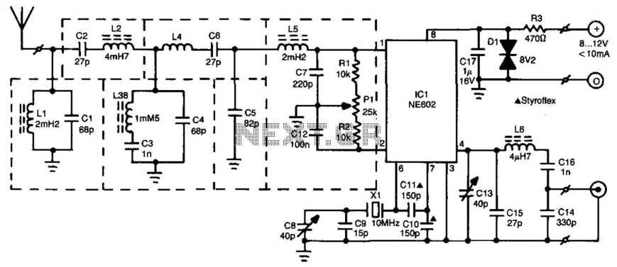
The radio beacon band ranges from 280 to 516 kHz. Each beacon transmits a unique AM-modulated Morse-coded callsign on a designated frequency. To receive distant beacons, the aerial signal is processed through a band-pass filter that effectively attenuates longwave...
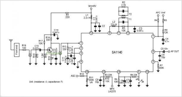
The SA1691 is a monolithic integrated circuit designed for radio cassette tape recorders, clock radios, and headphone radios. This IC includes all functions from the antenna to the audio power amplifier of AM/FM radio, produced by Silan. The SA1691 integrated...
A crystal oscillator circuit is a straightforward oscillator circuit that can be easily understood through its schematic diagram. It serves as a replacement for a conventional oscillator network, which typically consists of an LC combination. This simplicity is also...

NE5532DR absolute maximum ratings: (1) Supply voltage: VCC+ 22 V; VCC-: -22 V; (2) Input voltage, either input VCC ±; (3) Input current: ±10 mA; (4) Duration of output short circuit: Unlimited; (5) Package thermal impedance, JA: D package...
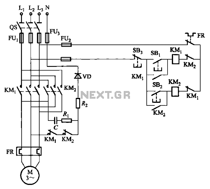
The circuit depicted in Figure 3-146 eliminates the need for a step-down transformer by utilizing the principle of energy storage through capacitor discharge for braking. It can be employed to frequently start and stop a motor with a power...