
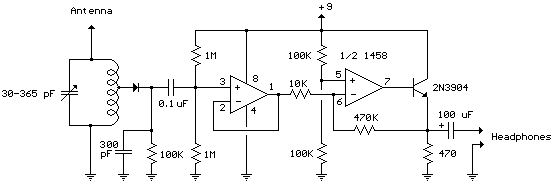
Radio Beacon Converter
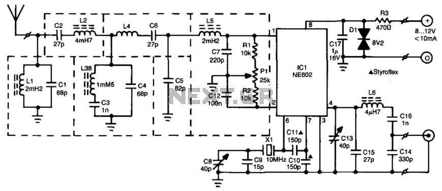
The radio beacon system operates within a specified frequency range, facilitating the transmission of Morse-coded callsigns for identification purposes. The band-pass filter serves a dual role: it not only filters out unwanted signals but also matches the impedance levels between the aerial and the mixer IC1, ensuring efficient signal processing. The mixer circuit is crucial as it shifts the frequency of the incoming beacon signal to a range compatible with standard shortwave receivers. This frequency conversion is essential for practical reception, as the original beacon frequencies are not directly accessible by typical shortwave equipment.
The design of the circuit includes specific considerations for shielding sensitive components, which is vital for minimizing electromagnetic interference and ensuring stable operation. The alignment process is critical for achieving optimal performance. By utilizing an SSB receiver, the user can fine-tune the oscillator frequency to achieve a zero beat condition, which indicates that the local oscillator and the incoming signal are in phase, maximizing the signal strength. The subsequent detuning process allows for the identification of the beacon signal, which can be adjusted for clarity and volume, ensuring that the output is not only audible but also of high quality.
In summary, this radio beacon receiver circuit exemplifies a well-engineered solution for receiving and decoding Morse-coded signals from distant beacons, incorporating essential filtering, impedance matching, and alignment techniques to enhance performance and usability within the designated frequency range. The radio beacon band extends from 280 to 516 kHz. Each beacon has its own characteristic AM"-modulated morse-coded callsign that is transmitted on a specific frequency. To be able to receive distant beacons, the aerial signal is passed through a band-pass filter that effectively suppresses longwave and mediumwave signals. The filter also converts the aerial impedance, Zm, from about 10 KOhmhm to the input impedance of mixer IC1, which is about 1 KOhmhm.
The mixer adds or subtracts the received signal to/from the local oscillator signal so that the beacon signal can be received on a normal shortwave receiver. The resulting frequencies are from 9.72 to 9.48 MHz or from 10.280 to 10.516 MHz. In the construction of the converter, some components must be surrounded by a metal shield, as indicated by dashed lines on the PC board layout.
The circuit is aligned with the aid of an SSB receiver, to which the output of the converter is connected. Tune the receiver to 10 MHz and adjust the oscillator frequency of the converter with C8 for zero beat.
Next, detune the receiver slightly until you hear a pleasant whistle, which is adjusted for minimum level with the aid of PI. Finally, tune to a beacon transmitting at or about 300 kHz and adjust C13 for maximum sound output. 🔗 External reference
Related Circuits
Most small internal combustion engines commonly used in the model-building world utilize glow plugs for starting. Unfortunately, glow plugs have an operating... Glow plugs are essential components in many small internal combustion engines, particularly in the context of model building....
The diagram above illustrates a radio remote control dimmer circuit. This circuit utilizes a micro radio transmit/receive module in conjunction with a light modulation ASIC, resulting in a compact and easily producible design. It operates reliably and features a...
There are many individuals interested in listening to frequencies within the VHF range of 108 to 132 MHz. This VHF AM converter is designed to convert signals from a frequency band of 106 to 150 MHz, allowing users to...
The following schematic illustrates the Simple Op-Amp Radio Circuit Diagram sourced from bowdenshobbycircuits.info. This Simple Op-Amp Radio essentially functions as a crystal radio. The Simple Op-Amp Radio Circuit utilizes an operational amplifier (op-amp) to enhance the performance of a basic...
The VGA-to-Scope converter schematic has been simplified by removing op-amp buffers and inverters. A 1 Megohm potentiometer can be used instead of a continuous current supply to charge the capacitor from a 5V source. Proper placement of the potentiometer...
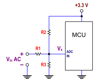
The ATtiny24 microcontroller's ADC is utilized to record an AC signal, which operates within a voltage range of 0 to 3.3V. A precision rectifier is employed to eliminate the negative portion of the signal. The circuit incorporates an LMC6484...