
Transistor sorter-tester
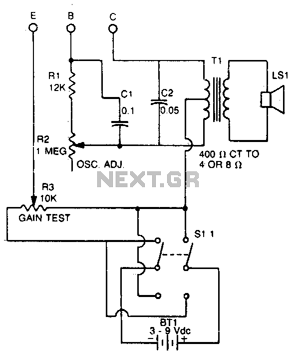
The transistor tester is designed to evaluate the polarity and gain of bipolar junction transistors (BJTs), which are essential components in various electronic circuits. The primary function of this device is to discern whether a transistor is of the PNP or NPN type. This is achieved through a simple interface that connects the transistor leads to the tester.
Upon connection, the tester applies a small voltage to the transistor and measures the resultant current flow. If the transistor is functioning correctly, an audible signal will be emitted, indicating that the transistor is operational and providing information about its gain, which is crucial for understanding its performance in a circuit.
Furthermore, this tester can serve as a GO/NO GO device. This feature is particularly useful for matching unmarked transistors, which may not have clear labeling for their type or specifications. By providing a straightforward pass/fail indication, the tester simplifies the process of identifying suitable replacements or matching components in circuit design and repair.
The design of the tester typically includes a visual display or LED indicators alongside the audible signal, enhancing usability. The circuit may incorporate a microcontroller or dedicated IC to process the input signals from the transistor and generate the necessary outputs. This ensures accurate readings and reliable performance, making the tester an invaluable tool for electronics engineers and hobbyists alike.This tester checks transistor for polarity (PNP or NPN). An audible signal will give an indication of gain Tester can also be used as a GO/NO GO tester to match unmarked devices. 🔗 External reference
Related Circuits
The following circuit illustrates a 2000W Power Amplifier Circuit Diagram. This circuit utilizes the BC560C transistor. Features include a robust design. The 2000W power amplifier circuit is designed to deliver high output power suitable for various applications, including audio amplification...
The following circuit illustrates a UHF Indicator Wavemeter Circuit Diagram. This circuit utilizes dual BF494 transistors. Features: the oscillator is... The UHF Indicator Wavemeter Circuit is designed to measure and indicate the frequency of ultra-high frequency (UHF) signals. The circuit...
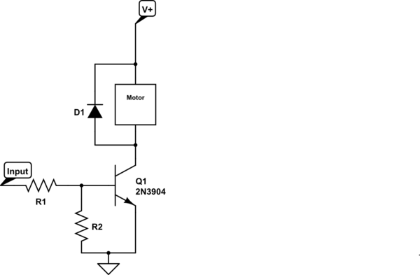
Control a small 5V motor using an external power supply by triggering a transistor with an Arduino. The transistor in use is an NPN type, specifically the 2N3904. To control a small 5V motor using an Arduino and an NPN...
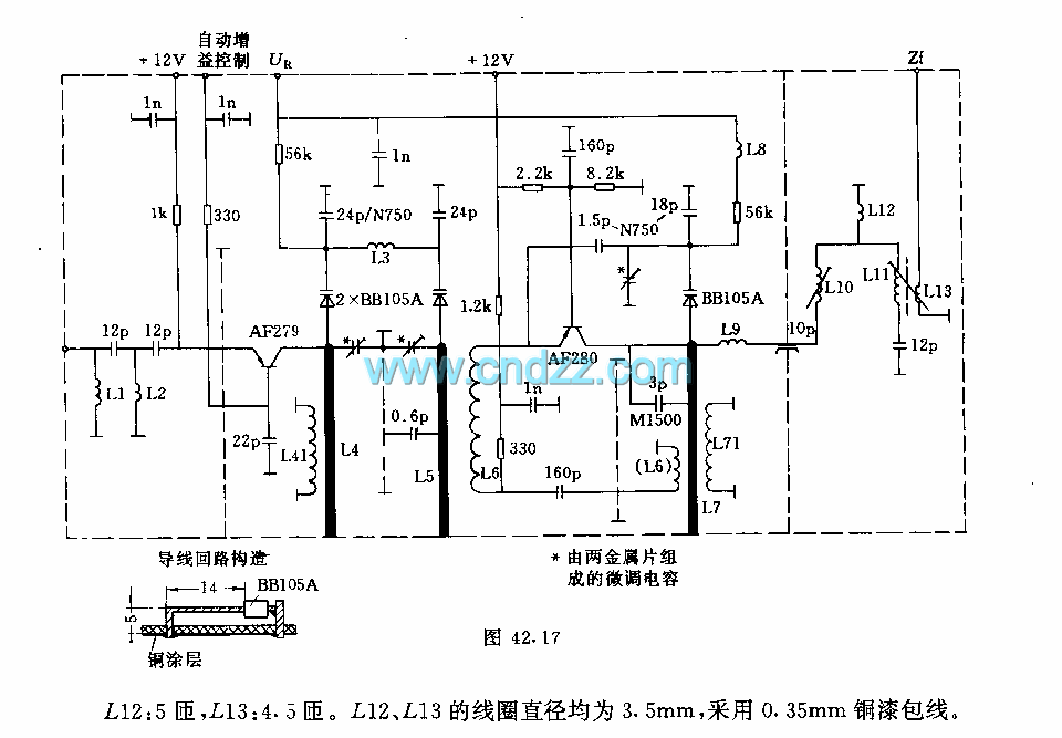
The circuit features an adjustable prestage utilizing the AF279 transistor, while the natural oscillation mixer stage employs the AF280 transistor. The power circuit is mounted on a board with copper coating. The main coil specifications are as follows: L1,...
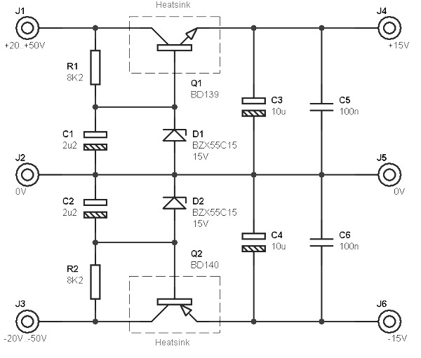
This circuit is designed to be integrated into an existing circuit, such as an audio amplifier, which already supplies symmetric voltages of +20V/-20V and +50V/-50V. The schematic diagram is derived from a dual polarity power supply circuit providing +/-...
An old RC car is available, but it lacks the transmitter. A custom receiver/transmitter has been built using a microcontroller and a 2.4 GHz transceiver. However, there is uncertainty regarding the functionality of the car's original H-Bridge circuit. The H-Bridge...