
ir infrared detector circuit diagram
An infrared (IR) detector circuit can be designed to test the functionality of remote control units by detecting the IR signals they emit. The basic components of such a circuit include a photodiode or phototransistor, which serves as the IR light sensor, and an LED or a buzzer to indicate the presence of the IR signal.
The circuit operates by positioning the photodiode in the line of sight of the remote control. When the remote control is activated, it emits an IR signal that the photodiode detects. The photodiode generates a small current in response to the incoming IR light. This current can be amplified using a transistor to drive an LED or buzzer, providing a visual or audible confirmation that the remote control is functioning properly.
To build the circuit, the following components are typically required:
1. Photodiode or phototransistor (e.g., BPW34 or similar)
2. NPN transistor (e.g., 2N3904 or similar) for signal amplification
3. Resistors (for biasing the transistor and limiting current to the LED)
4. An LED or a buzzer for output indication
5. A power supply (typically a 9V battery or a similar DC source)
The circuit can be assembled on a breadboard for prototyping before finalizing the design on a printed circuit board (PCB). Care should be taken to ensure proper orientation of the photodiode and other polarized components. Additionally, the circuit should be housed in a suitable enclosure to prevent damage and ensure ease of use.
By utilizing this IR detector circuit, users can quickly diagnose whether their remote control is operational, enabling them to troubleshoot issues effectively and maintain their control over television viewing.Men in particular enjoy the convenience of television remote controls often to the annoyance of their female partners. Men apparently want to know what they re missing when the TV is tuned to a particular program, so they like to keep zapping to other channels.
With the remote control in their hands, they feel like they are the lord and master of the TV set. They are thus completely at a loss if the remote control doesn t work properly. There are many reasons why a remote control unit can malfunction, such as defective IR receiver in the TV set, a defect in the remote control, or empty batteries. Here a tester that can determine whether the remote control unit still emits an IR signal can come in handy.
If you want to keep the IR reins ?rmly in hand, you can build your own IR detector.. 🔗 External reference
Related Circuits
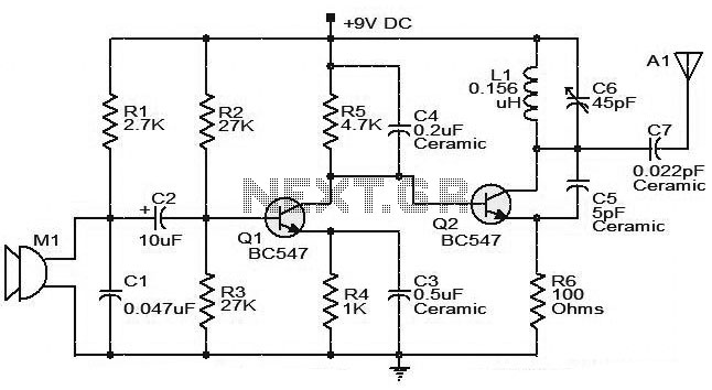
The moderate power FM transmitter circuit employs two transistors. The voice signals picked up by the microphone will be amplified by the transistor. The described FM transmitter circuit utilizes two transistors to facilitate the modulation and amplification of audio signals....
The welder no-load power saver circuit consists of a current detection control circuit and a power saving control circuit, as illustrated in the accompanying chart. The current detection control circuit includes a current transformer (TA), a bridge rectifier (UR),...
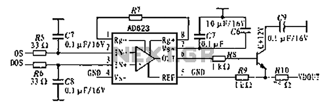
The AD623 is an integrated 3-way amplifier that can operate with either a single or dual supply. It features high common-mode rejection ratio (CMRR) and low voltage drift, along with programmable gain control via an external resistor. All components...
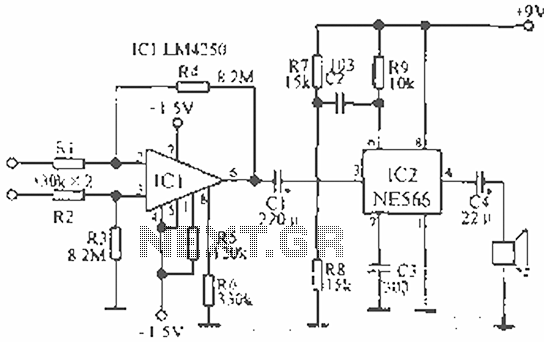
The circuit is designed for teaching demonstrations or experiments to hear the electrocardiogram (ECG) signal voltage. The ECG signal voltage is amplified by the LM4250 operational amplifier, which is connected to a voltage-controlled oscillator (NE566) to modulate the oscillator...
The circuit is a simple op-amp but with two diodes (the transistor b-e junctions in the feedback to split the feedback for positive and negative outputs. On positive output from the stepper coil the top transistor turns on, on...
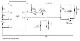
The values of the LM56 thermostat project circuit diagram for resistors R1, R2, and R3 at the travel points VT1 and VT2 can be determined using the following equations. This electronic circuit thermostat with the IC LM56 serves as...