This circuit is a digital panel meter (DPM) featuring an analog bar graph display and a 3.5-digit digital display. The ICL7107 is configured for 200mV input. The U4A operational amplifier (LF353) amplifies the 200mV full-scale input to the required level for the LM3914 display circuit. D13 and D14 serve as clamping protection diodes. The P1 trimpot is adjusted to achieve a reading of 1000 counts when a 100.0 mV signal is applied at the input. The R8 trimpot is adjusted to ensure that the fifth LED activates at a 100mV input. An analog recorder with an ink-pen plot against time is an effective method for process analysis, as many systems are better understood through graphs rather than tables of numbers. A computer-based data logger enhances this method by allowing the measurement and plotting of various types of data over extended periods. This circuit is a straightforward LED lamp design for educational purposes, with the first draft schematic labeled as version 1.0, which may require enhancements for higher power lighting applications. The LM317 is configured here for approximately 6.4V DC. The Q3 BC547 transistor limits the current, and the resistance value of R3 can be selected accordingly, ideally rated at 0.5W. The Ni-Cd battery pack (1.2V x 4) is protected from over-current and over-voltage conditions by this circuit. The IRF540 MOSFET or any equivalent component, along with the Q2 BC547 transistor, forms a current source. This LED analog meter can also function as a resistance meter and low-impedance voltmeter for battery levels. To measure battery voltage, the reference resistor divider network (R5, R12, R17, etc.) can be modified as needed. The configuration shown is for four LEDs; for twelve or more LEDs, three LM324 operational amplifiers can be used in a cascading arrangement. This circuit is not suitable for measuring voltage levels from high-impedance sources but is effective for battery voltage tests. To convert it into a continuity tester, R27 must be shorted, and R23 should be set to 5 ohms. The black probe should have a built-in resistance of 2 ohms. The proximity switch operates over a wide voltage range, from 8V to 18V DC. The D3 diode protects against reverse power supply connections, while U1 regulates the supply to +5V, with -5V derived from the U2 555 oscillator, which serves dual purposes. The circuit operates by detecting objects through reflected infrared light, which can be housed in a cylindrical enclosure similar to an inductive proximity switch. This setup is also useful for level detection in colored liquids like oil, exhibiting some immunity to ambient sunlight by detecting AC pulses. The IC 555 functions as an astable oscillator, flashing the infrared LED (D1) at high speed. Objects close to this LED reflect light, including ambient light, which may also include sunlight. Various types of infrared LEDs and diodes are available, each with specific polarities. The circuit illustrates a voltage doubler in conjunction with a 555 timer. The LM555 can deliver up to 200mA, with both Vcc and Gnd available. The 555 timer is advantageous due to its high drive capability and mixed design, functioning as an analog programmable chip. It possesses features akin to a mini ADC due to its voltage-controlled oscillator (VCO) function, allowing for the creation of simple switching supplies. Power line modems have been designed using this chip, which is also applicable in timers, modulators, trip relays, and various musical circuits. This design represents a constant current source LED driver. When the upper NPN transistor is activated by a voltage through a 4.7k resistor, the LED illuminates, assuming the absence of the lower NPN transistor. The current through the LED and NPN is limited by a resistor; typical values are around 20mA, although 15mA is preferable to prevent damage to the LED and transistor. The BC547 transistor has a rating of 100mA and 40V.This Circuit is a DPM or digital panel meter. It has a analog bar graph display and a 3-1/2 digit digital display. ICL7107 is used in the 200mV configuration. U4A opamp LF353 amplifies the 200mV Full scale input to the level required for the LM3914 display circuit. D13-D14 are clamping protection diodes. Adjust P1 trimpot for a reading of 1000 cou nts when a 100. 0 mV signal is fed at Vin. Adjust R8 trimpot to get the 5th led to just turn on at 100mV input. Sometimes a analog recorder with a ink-pen plot against time is a very good way of process analysis. Many systems are better studied using graphs not tables and lists of numbers. A Computer based data-logger gives greater power to this methods. You can measure and plot graphs of various types and at different points and for much longer periods. This is a easy to build LED lamp circuit for Learning and building skills. This is the first draft schematic V 1. 0. It will need improvements for Higher Power Lighting. From Schematics of delabs I will give a short summary, The LM317 here configured for around 6. 4V DC. The Q3 BC547 limits the current, you can select R3 to suit, make it 1/2W. The Ni-Cd battery pack 1. 2 * 4 will not get Over-Current or Over-Voltage due to this circuit. The IRF540 Mosfet or any other equivalent you have around, along with Q2 BC547 forms a current source for the Read More This is a LED Analog Meter, This can be used as a Resistance Meter and Low Impedance Voltmeter for Battery Levels.
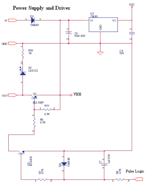
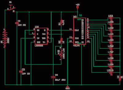
To measure battery voltage, the R5-R12-R17 etc. part of the Reference Resistor Divider Network can be modified to suit. Shown here is for 4 LEDs, Use Three LM324 for 12 or More LEDs and Cascade as shown. This cannot Measure Voltage levels from High Impedance Sources, will work for Battery Voltage Tests. To make it into a Continuity tester. R27 must be a short and R23 5 Ohms. The Black probe should have a Built in Resistance of 2 Read More The proximity switch can work for a wide range of power, from 8v to 18v DC, D3 protects reverse power supply connections, and U1 regulates the supply to +5v, -5v is derived from U2 555 oscillator which serves dual purpose. Circuit Operation The infra red diode D2 detector gets the reflected light from LED and some ambient light, The forward voltage drop of D2 will vary with the amount of light falling on it.
Ambient light causes a DC component and the pulsing light from D1 causes an AC component. The capacitor C6 blocks DC and only transfers AC Read More This circuit is used to detect objects by reflected infrared light. It can be built into a cylindrical enclosure just like an inductive proximity switch. This is also useful as a level detector for colored liquids like oil. This has some immunity to ambient sunlight as it detects ac pulses. IC 555 is used as an astable oscillator and it flashes the Infra red LED D1 at a high speed, The object close to this LED reflects the light along with the ambient light which may also be sunlight.
IR Led`s and Diodes The types available are various and polarity Read More This circuit shows the voltage doubler working with a 555. LM555 has good drive 200mA, both Vcc and Gnd. 555 has the advantage of having a high drive as well as being a Mixed Design, Analog Programmable chip.
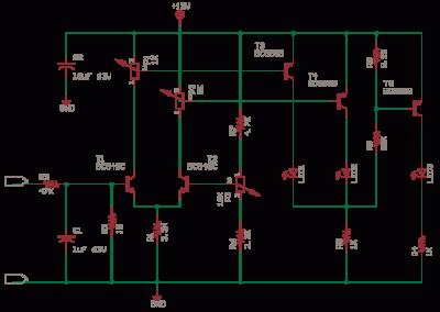
That may be a High Title for such humble a chip. It has the capability of a Mini ADC due to its VCO function. It could form even a simple switching supply. Power Line Modems have been designed using this chip. Timers, Modulators, Trip Relays and even a Timer for The Humble Bread Toaster. Musical circuits, Piano and Metronome Galore, it drives Read More This is a Constant Current Source LED Driver, When the LED driver Upper-NPN is driven by a voltage thru 4. 7K the LED lights up. Assume that the Lower-NPN at bottom is absent. The current via LED and NPN is limited by R. 20mA may be ok 15mA even better. Or LED blows even transistor goes. BC547 is like 100mA-40V-2 🔗 External reference
This is a constant current source using a FET. It serves as a simple replacement for a series resistor to limit current. The N-Channel FET BF256C can provide a current of 15mA. Before using integrated circuits, it is advisable...
The 555 Astable generates a clock for this circuit, functioning as an oscillator that produces a square wave output at pin 3. This output is counted by the CD4017 decade counter, which creates a running lights effect. The CD4017...
This LED series will blink alternately. The operation is determined by the NE555 integrated circuit, with transistors used to reinforce each section (20 upper, 20 lower) for optimal performance. The 555 circuit described below functions as a flashing bicycle...
We use cookies to enhance your experience, analyze traffic, and serve personalized ads.
By clicking "Accept", you agree to our use of cookies.
Learn more