
Cuckoo sound Generators

The circuit design employs a combination of integrated circuits, discrete components, and transistors to achieve the desired audio effect. The use of IC1 as a square wave generator allows for precise control over the frequency of the generated tones, while the trimmer resistors enable fine-tuning to achieve the correct pitches. The transformation of the square wave to a quasi-sinusoidal waveform is crucial for mimicking the natural sound of a cuckoo, as it provides a smoother audio output that is more pleasing to the ear.
The inclusion of a noise generator (Q1 and R6) adds richness to the sound, making it more realistic. The gating function of Q2 is essential for controlling the dynamics of the sound, allowing for a more expressive output that can simulate the nuances of the cuckoo call. The timing of the sound and pauses is managed through a clock signal from IC2A, which ensures that the two-tone sequence is well-coordinated and rhythmic.
In practical applications, the circuit can be adapted for various uses beyond doorbells, such as in toys, alarms, or sound effects in multimedia projects. The flexibility of connecting to external amplifiers or recording devices further enhances its usability. Overall, this circuit exemplifies a creative approach to sound synthesis, leveraging basic electronic components to produce a recognizable and engaging auditory effect.This circuit generates a two-tone effect very much alike the cuckoo sound. It can be used for door-bells or other purposes thanks to a built-in audio amplifier and loudspeaker Used as a sound effect generator it can be connected to external amplifiers, tape recorders etc. In this case, the built-in audio amplifier and loudspeaker may be omitted an d the output taken from C8 and ground. There are two options: free running, when SW1 is left open, and one-shot, when SW1 is closed. In this case a two-tone cuckoo sound will be generated each time P1 pushbutton is pressed. IC1 is wired as a squarewave generator and produces both tones of the cuckoo sound. The frequency of the higher one (667Hz) is set by means of Trimmer R2. When IC2D output goes low, a further Trimmer (R22) is added to IC1 timing components via D6, and the lower tone (545Hz) is generated. To imitate closely the cuckoo sound, the squarewave output of IC1 is converted to a quasi-sinusoidal waveform by R3, R4, C3 and C4, then mixed with the white noise generated by Q1, R6.
Q2 has two purposes: it mixes the two incoming signals and gates the resulting tone, shaping its attack and decay behavior by means of the parts wired around its Emitter. The various sound and pause timings for the circuit are provided by the clock generator IC2A driving the decade counter IC3.
Some output pins of this IC are gated by IC2C, IC2D and related components to drive appropriately the sound generator and the sound gate. When SW1 is left open the circuit operates in the free-running mode and a cuckoo sound is generated continuously.
When SW1 is closed, the circuit generates two tones then stops, because a high state appears at the last output pin (#11) of the decade counter IC: therefore the count is inhibited by means of D1 feeding pin #13. Best results will be obtained if the two tones frequencies are set precisely, i. e. 667Hz for the first tone and 545Hz for the second: in musical terms this interval is called a Minor Third.
Obviously a digital frequency counter, if available, would be the best tool to setup R2 and R22, but you can use a musical instrument, e. g. a piano or guitar, tuning-up the notes accurately by ear. 🔗 External reference
Related Circuits
This is a metronome circuit that produces a mechanical sound characteristic. A metronome with a mechanical sound character enhances the enjoyment of musical practice and performance. The metronome circuit is designed to generate a rhythmic sound that aids musicians in...
This is a straightforward sound effect generator based on the single sound generator chip UM3561. The UM3561 can produce four types of sound effects. Its basic operation involves generating a sound signal, which is then delivered to a 2N3706...
Surround Sound Decoder circuit diagram. The circuit's operation begins when the stereo sound signal carries surround sound information through the master volume section. This drives the Left channel (Lch), which is connected to Model TL072 IC1A and IC1B, with...
This circuit uses a UM3561 IC to produce four different sound effects. Nothing too complicated here. The IC produces all the sound effects, the output at Pin 3 being amplified by the transistor. A 64 ohm loudspeaker can be...
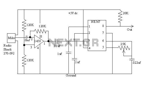
The detector is a bit more complex. It amplifies a microphone and sends the resulting signal to an NE567 tone decoder. The amplifier is half of a 1458 opamp. The two 120K resistors attached to pin 3 keep the...
This circuit uses the Holtek HT2884 IC to produce 8 different sound effects. All sound effects are generated internally by the HT2884 IC. Power is a 3 Volt battery, but the IC will work with any voltage between 2.5...