
Sound Effects Generator

The circuit utilizes the UM3561 integrated circuit (IC), which is specifically designed for generating sound effects. The UM3561 can produce a variety of audio signals, which are commonly used in toys and novelty devices. The circuit configuration allows for four distinct sound effects to be selected using a two-pole, four-way switch.
In this design, the output from Pin 3 of the UM3561 is connected to a transistor, which serves to amplify the audio signal before it is sent to the speaker. The transistor acts as a signal booster, ensuring that the sound produced is loud enough for practical use. The output can drive a loudspeaker, and while the circuit design specifies a combination of a 56-ohm resistor and an 8-ohm speaker, a 64-ohm loudspeaker can be used as an alternative. This flexibility allows for variations in sound output based on the components available.
The sound effects generated by the UM3561 include a police siren, fire engine sound, ambulance siren, and a machine gun effect, corresponding to the four positions of the switch. Each position connects different internal configurations of the IC, which alters the frequency and waveform of the output sound, creating distinct audio experiences.
The UM3561 IC is manufactured by UMC, and it is important to note that sourcing this component may require checking with electronics suppliers, as availability can vary. This circuit is relatively straightforward, making it suitable for hobbyists and those looking to explore sound generation in electronic projects.This circuit uses a UM3561 IC to produce four different sound effects. Nothing too complicated here. The IC produces all the sound effects, the output at Pin 3 being amplified by the transistor. A 64 ohm loudspeaker can be substituted in place of the 56 ohm resistor and 8 ohm loudspeaker. The 2 pole 4 way switch controls the sound effects. Position 1 (as drawn) being a Police siren, position 2 is a fire engine sound, 3 is an ambulance and position 4 is a machine gun effect. The IC is manufactured by UMC and was available from Maplin electronics code UJ45Y. At the time of writing this has no 🔗 External reference
Related Circuits
The circuit was designed to create a frequency generator that consists of seven steps during operation. It includes a crystal oscillator, which is an electronic circuit made of... The frequency generator circuit operates through a series of seven distinct steps,...
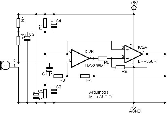
After conducting new experiments on sound analysis, a different design for the microphone amplifying section has been developed. The entire circuit is powered by a clean voltage supply ranging from +5V to +12V, which is filtered by capacitor C5....
This sawtooth wave generator provides a sweep signal at output 1 and a synchronization output at output 2, which activates when the sawtooth wave returns to its starting point. The frequency of the sawtooth wave signal is calculated using...

This window generator utilizes a single LM324 operational amplifier and includes two adjustable set points. When the two comparators formed by U1B go high, LED1 illuminates. When U1C goes high, the LED turns off. Hysteresis is implemented using 10...
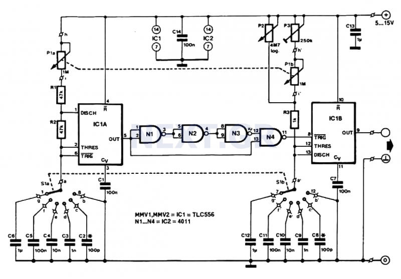
This pulse generator produces square pulses ranging from 1Hz to 100KHz with an adjustable pulse width of nearly 0-100%. It operates on a voltage of 5-15V, making it suitable for both TTL and CMOS circuits. This device is essential...
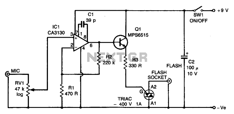
The circuit utilizes an operational amplifier (IC1) configured in a non-inverting amplifier mode. Resistors R1 and R2 establish a gain of approximately 500. The variable resistor RV1 (sensitivity) adjusts the bias of the non-inverting input to the negative supply...