
Current Limit Circuit for Voltage Regulator

The circuit described is designed to enhance the performance of a voltage regulator by integrating a current limiting feature. This is particularly beneficial in applications where overcurrent conditions may occur, potentially damaging sensitive electronic components.
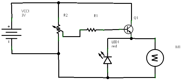
The circuit typically consists of a voltage regulator IC, such as the LM317 or a similar linear regulator, which provides a stable output voltage. To implement the current limiting function, a shunt resistor is placed in series with the load. This resistor allows for the measurement of the load current.
An operational amplifier (op-amp) is used to monitor the voltage across the shunt resistor. When the current exceeds a predetermined threshold, the op-amp output changes state, triggering a control mechanism that adjusts the regulator output. This could be achieved through a transistor or a MOSFET that effectively reduces the regulator's output voltage, thereby limiting the current flowing to the load.
Additional components may include a reference voltage source for the op-amp, ensuring accurate current threshold settings, and capacitors to stabilize the circuit and filter out noise. Proper selection of component values is crucial to achieve the desired current limit without compromising the voltage regulation performance.
This circuit is particularly useful in battery-powered devices, power supplies, and any application where protection against overcurrent is necessary. By adding this functionality, the reliability and longevity of the overall system are significantly improved.This is a low cost circuit that adds precise current limit functionality to a voltage regulator. 🔗 External reference
Related Circuits
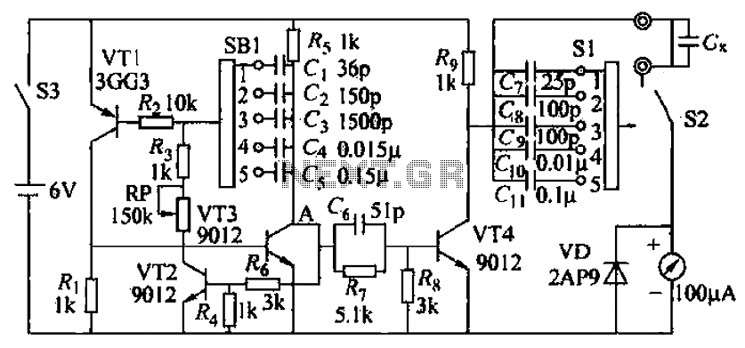
A capacitive measuring instrument is a direct reading device that measures the capacitance of a circuit. This instrument is capable of measuring capacitance values ranging from a few picofarads to 0.1 microfarads, with specific ranges of 25 pF, 100...
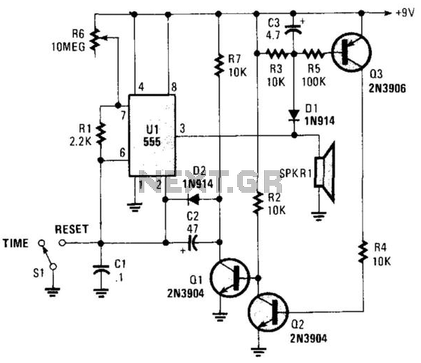
This circuit operates in astable mode and produces a tone at the end of the first period, which can last several minutes. When switch SI is in the time position, transistor Q3 is turned off because pin 3 of...
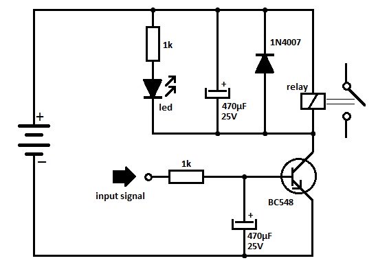
One of the serious problems in relay-operated circuits is the relay clicking or chattering during the on/off operation of the relay driver transistor. This issue can lead to unreliable circuit performance and may cause premature wear of the relay...
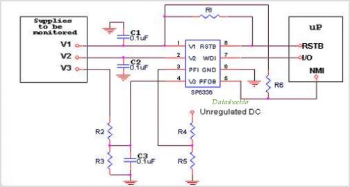
Introduction The SP6648 integrated synchronous boost regulator is a compact circuit that provides ultra-high efficiency drive current for an LED flashlight using a Luxeon I light source. The circuit is configured to deliver a constant output current of 350mA...
In a prior post titled "Timing is Everything," the application of PWM (Pulse Width Modulation) signals for controlling devices such as LEDs was discussed. This technique is particularly beneficial when working with digital devices, including microchips and microcontrollers, which...

This inverter circuit is designed to power electric razors, stroboscopes, flash tubes, and small fluorescent lamps using a 12-volt car battery. Unlike typical feedback oscillator inverters, this design features a separate oscillator from the output stage, allowing for easy...