
Transistor Relay Driver Circuit
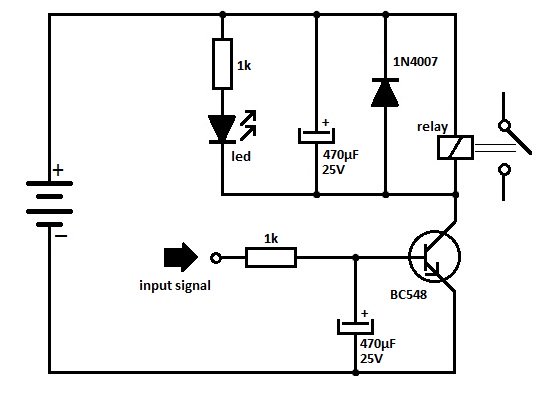
In relay-operated circuits, the phenomenon known as relay chattering occurs when the relay fails to maintain a stable state during the switching process. This instability is often caused by oscillations in the control signal driving the relay driver transistor. When the transistor is turned on or off, any noise or fluctuations in the control signal can cause the relay to rapidly switch between its on and off states, resulting in a clicking sound and potential damage to the relay contacts due to excessive wear.
To mitigate this issue, several strategies can be employed. One common solution involves adding a snubber circuit across the relay contacts to suppress voltage spikes that may occur during switching. Additionally, implementing a debounce circuit in the control signal path can help to filter out noise and ensure that only clean, stable signals are used to drive the relay.
Another approach is to utilize a relay driver circuit that incorporates hysteresis. By designing the driver with a small amount of positive feedback, the circuit can create a threshold that prevents the relay from toggling rapidly. This method stabilizes the on and off states, thus reducing chattering and enhancing the overall reliability of the circuit.
Furthermore, selecting a relay with appropriate specifications for the application, including contact ratings and response times, can also play a crucial role in minimizing chattering. Using solid-state relays can be advantageous as they typically do not exhibit the same mechanical wear as electromagnetic relays, thus providing a more reliable alternative for applications sensitive to such issues.
In summary, addressing the problem of relay chattering requires careful consideration of circuit design, component selection, and noise management to ensure stable operation and longevity of the relay system.One of the serious problems in relay operated circuits is the relay clicking or chattering during the on/off of the relay driver transistor. This problem i.. 🔗 External reference
Related Circuits
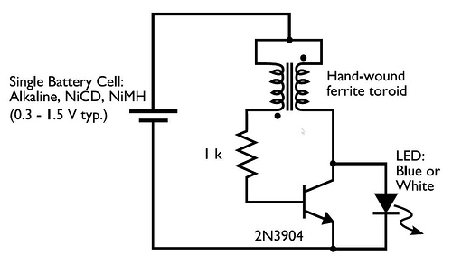
This circuit is commonly referred to as a Joule Thief, and it has been frequently encountered in various electronics videos on YouTube. The Joule Thief is a simple, low-cost circuit designed to extract energy from a single-cell battery, particularly when...
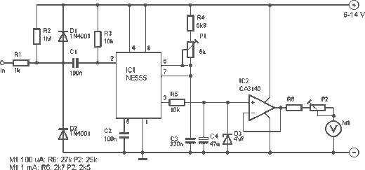
This is a nice design for people who have no tachometer in the car or on the bike. The circuit uses two ICs: an NE 555 and a CA 3140. The input of the circuit is connected to the...
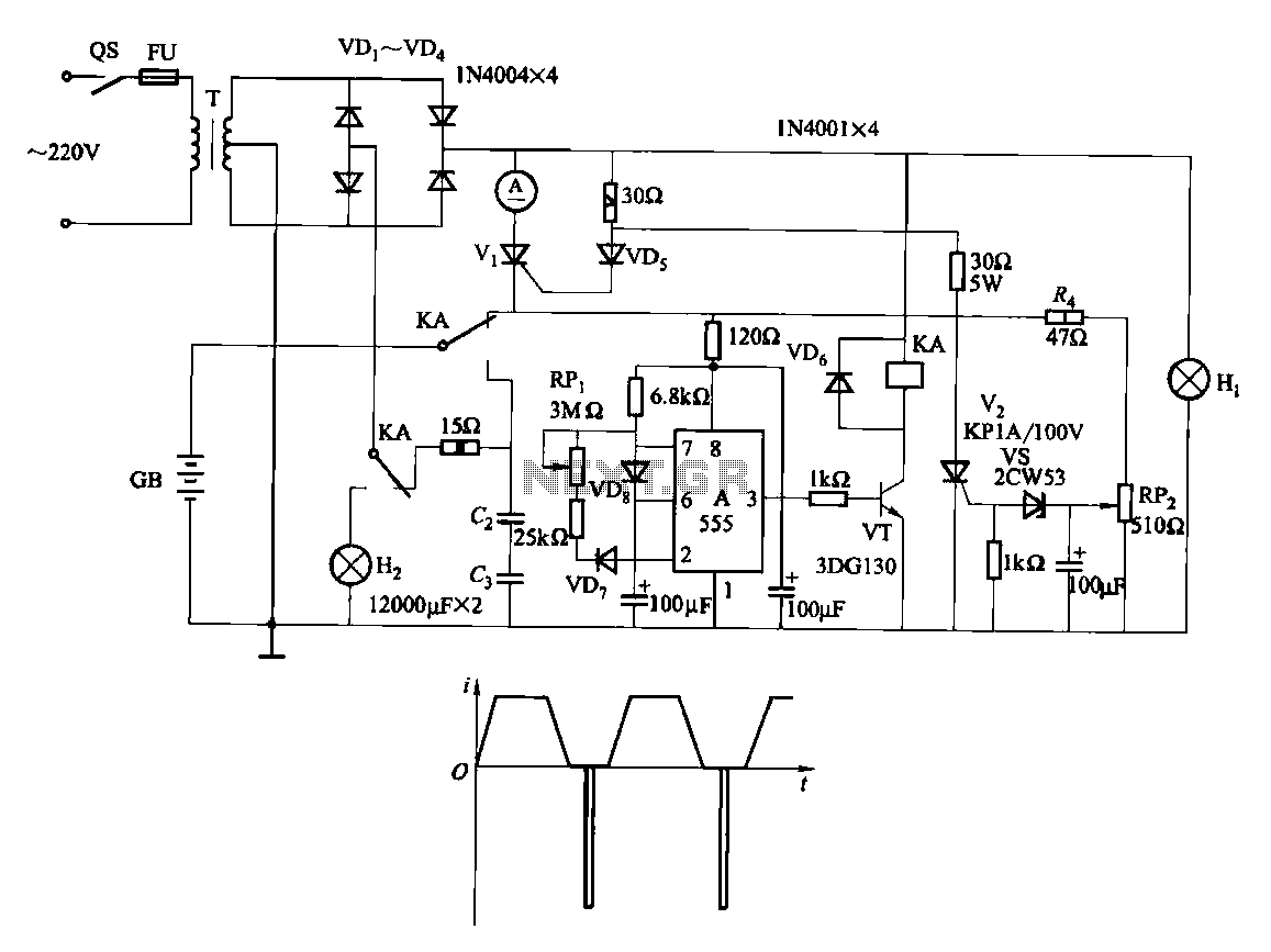
Fast and efficient charging is significantly higher than conventional charging, achieving a current charge that is ten to several times greater. When the battery voltage reaches a predetermined level (known as the polarization point), polarization within the cell becomes...
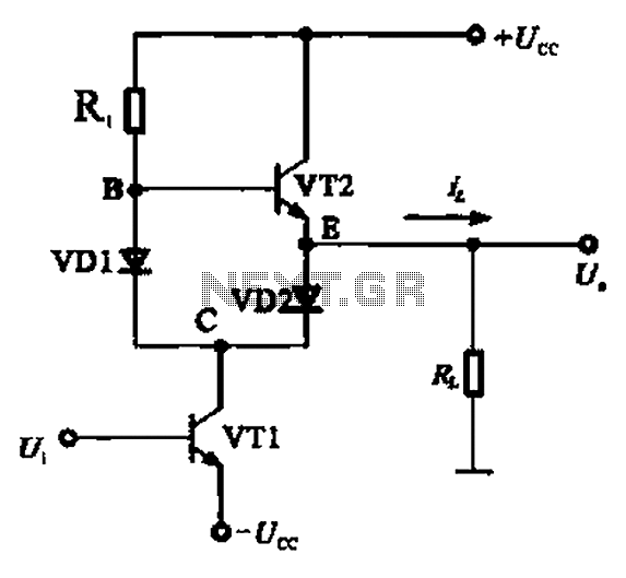
A Class AB output stage circuit is coupled with diodes, as illustrated in Figure 10-8. The static bias circuit for transistor VT1 (not shown) is adjusted so that the output at point E is at ground DC voltage UE....
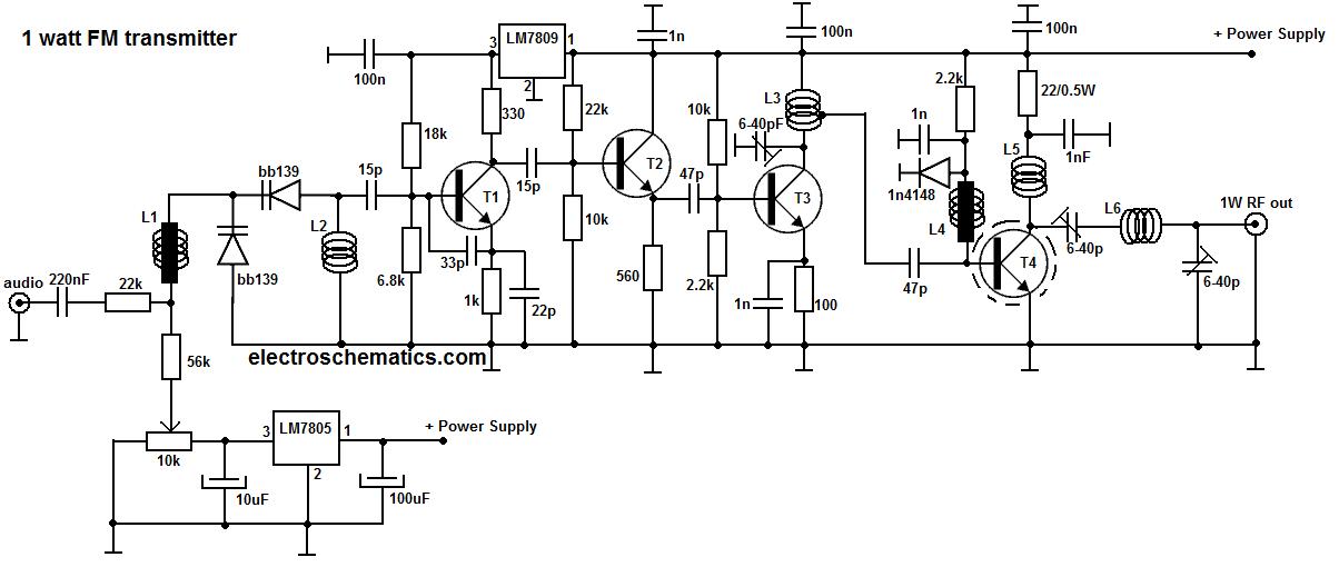
This portable FM transmitter features a limiter, a microphone amplifier, and PLL digital tuning, all integrated onto a single circuit board. The RF power output can be switched between 1 W (high) and 0.2 W (low). The schematic is...
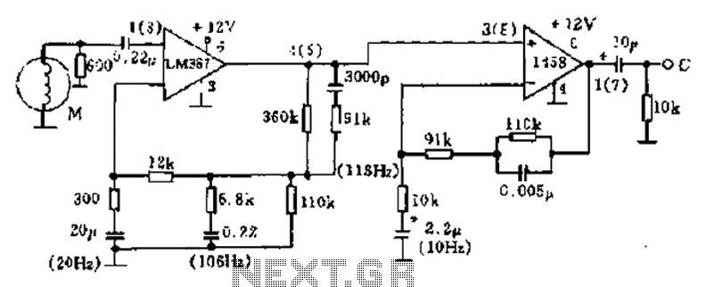
The phonograph pickup head is represented in the schematic as component M, which generates the pick-up signal and is processed through an LM387 amplifier circuit. The LM387 is part of the LM38X series, recognized for its advanced linear amplifier...