
Current Mirror for LEDs
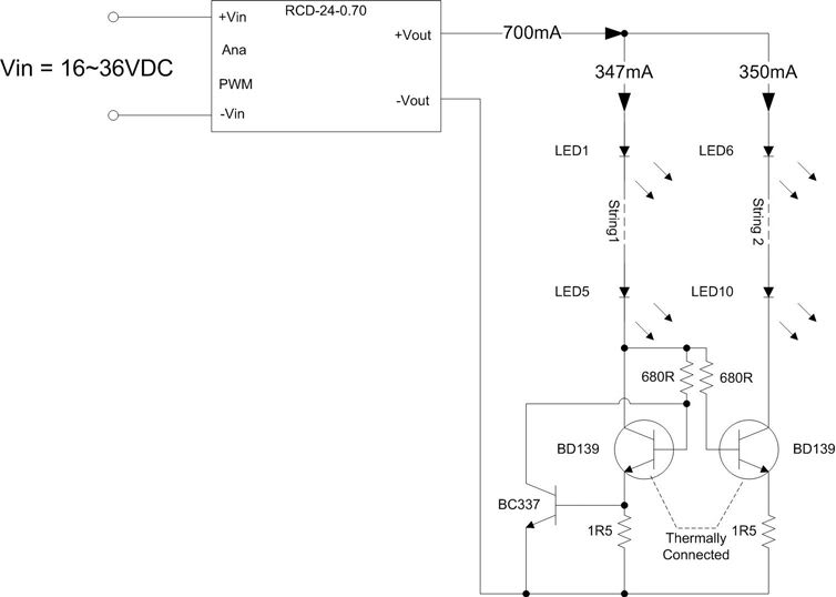
The BD139 transistor may encounter difficulties operating at 1150mA, as its gain significantly decreases beyond 400-500mA, potentially dropping to values as low as 8-10 at higher currents. For 1150mA operation with a gain of 10, a base current of 115mA would be required, resulting in a voltage drop across the 680 Ohm resistor of approximately 78V, necessitating either a higher gain transistor or a smaller resistor, or both. Additionally, the behavior of the overcurrent protection circuit must be considered. When the voltage across the 1.5 Ohm resistor exceeds approximately 0.7V, the BC337 begins to conduct, which limits the LED current by increasing the voltage drop across the BD139. The Meanwell driver will attempt to compensate by adjusting its output voltage to maintain the maximum current of 700mA, provided there is sufficient voltage headroom available.
The design of the circuit requires careful consideration of component ratings and values to ensure reliable operation and protection for the LEDs. The use of a higher gain transistor, such as the BC547 or similar, may improve performance under load conditions. Additionally, ensuring adequate heat dissipation for the components, especially the power transistors, is crucial to prevent thermal overload and maintain efficiency. The implementation of a robust current monitoring system can enhance the reliability of the LED strings, safeguarding against potential failures and extending the lifespan of the overall assembly. Proper layout and thermal management techniques should be employed in the PCB design to facilitate optimal performance of the LED driver circuit.I have one Meanwell LED driver of 27V, 2300mA on hand and will be running 2 strings of 6 LEDs in parallel. Should I follow the same circuit with same component value or should I need to change the value of the resistors to my configuration "The addition of a small signal transistor as a current monitor protects the LEDs from being overd
riven in the case of any LED failures. If LED1 LED5 fail open circuit, then the current in the second string falls to zero as before. However, if LED6 –LED10 fail, then the current increases in the first string until the voltage developed across the 1. 5 Ohm emitter resistor reaches around 0. 7V, thus turning on the BC337 transistor and pulling the base voltage of the power transistor to ground and limiting the current.
With the component values given in the circuit, the measured current limit was 445mA with String 2 open circuit. " That circuit will NOT work at 1. whatever amps. Replace the 1. 5s with ~. 47s, the BD139`s with something bigger (anything with a DC current gain over like 80 at 1A and a maximum continuous current of 2A or more) and the 680s maybe drop to 470.
Now that I think about it this circuit kinda sucks, if you get a transistor with a lower end gain its going to eat up a buttload of efficiency. That circuit will NOT work at 1. whatever amps. Replace the 1. 5s with ~. 47s, the BD139`s with something bigger (anything with a DC current gain over like 80 at 1A and a maximum continuous current of 2A or more) and the 680s maybe drop to 470.
Now that I think about it this circuit kinda sucks, if you get a transistor with a lower end gain its going to eat up a buttload of efficiency. If built as shown, string 1 is going to be clamped at 460ma or so, read the blue paragraph as to exactly how.
String 2 is going to take the rest of the current (1840ma or so) assuming there is enough headroom to cover the increased Vf at that current. Ok I take it back the circuit will work in that it lights up all the LEDs. Just make sure you heatsink the crap out of string 2 The point of this circuit is to save the remaining LEDs in the case of a failure.
That could get quite expensive. The second itteration of the circuit on that page will keep either side of the parallel array within the set current range set by the smaller resistor (about 0. 57 ohms to keep the current at no more than 1. 2A), regardless of which side fails. cptbjorn, everyone here is here to learn. If you know that something doesn`t work, educate us as to why and how to fix it, or show us a better way to do it opposed to taking a somewhat condesending tone towards those of use that don`t know.
I won`t say that I know everything. I learn new things every day. Help us learn something new Sorry bro didn`t mean to sound condescending, I just wanted to make sure someone didn`t fry their $$ LEDs. I definitely appreciate all you do around here, I guess I`m just used to my real life where people specifically do NOT want to know the boring nerdy details of how I fix stuff.
Anyways here we go, full version. First of all the BD139 is going to have issues running at 1150ma. While a good device for the original circuit, Its gain drops drastically after 4-500ma and could be as low as 8-10 at 1150ma (down from 80 or so originally). For 1150ma at gain of 10 it will need 1150/10=115ma of base current through the 680 ohm resistor, which equates to a.
115x680=78v! drop. We need a higher gain transistor or a smaller resistor (or both). The second problem is what actually happens when the overcurrent protection kicks in. When the voltage across the 1. 5R resistor goes above ~. 7v, the BC337 starts conducting. This limits the current through the leds by increasing the voltage drop across the left BD139. The Meanwell driver will try to compensate to make the circuit "take" the full 700ma by pegging its voltage output to the maximum it can. If you have 10v of headroom, that BD139 i 🔗 External reference
Related Circuits
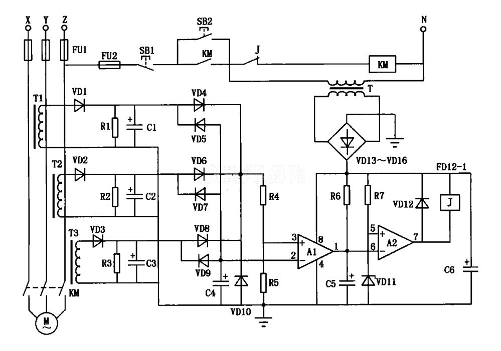
A current three-phase motor phase protection circuit is designed to detect three-phase current using homemade small current transformers T1, T2, and T3. The current signals are collected by rectifiers VD1, VD2, and VD3, while capacitors C1, C2, and C3...
The LM3915 is a monolithic integrated circuit that senses analog voltage levels and drives ten LEDs providing a logarithmic 3 dB/step analog display. LED current drive is regulated and programmable, eliminating the need for current limiting resistors. More: This...
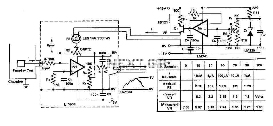
To amplify small current signals as an electron collector inside a vacuum chamber, it is advantageous for reasons related to noise and bandwidth to have a "head-amplifier" connected to the chamber. Operational amplifier 1 is a precision device featuring...

This circuit allows for the establishment of a maximum output current limit from a power supply unit (PSU). It is particularly beneficial when initially powering a project or conducting a soak test. By imposing an upper current limit, protection...
The constant current function module is disabled at the port junction, which has 13 terminals. When the module is turned OFF, the constant current ban port also becomes inactive. The constant current function is lost when the module is...
This article compares high-side and low-side amplifiers used for measuring battery charging currents. It recommends selection criteria for current-sense resistors and describes a high-voltage circuit breaker designed for overcurrent protection. High-side and low-side amplifiers are essential components in battery management...