
An Add-on Current Limiter

The circuit operates on the principle of current limiting through a feedback mechanism involving a power transistor and resistive elements. The diodes used in the circuit ensure that the base voltage of the transistor remains stable, which is crucial for maintaining consistent operation. The choice of R2 directly influences the maximum current output, and the relationship between voltage, current, and resistance follows Ohm's Law. When the load attempts to draw more current than the set limit, the feedback mechanism causes the transistor to reduce the output voltage, thereby protecting the circuit from overcurrent conditions.
In the enhanced schematic, the addition of an LED provides a visual indication of circuit status, offering a straightforward means for users to monitor the output without needing additional equipment. The buzzer feature further enhances usability, especially in scenarios where the circuit may be left unattended. This alert system is critical for preventing damage to components and ensuring safety during long-term tests.
The design's flexibility allows for customization based on user requirements. Components can be omitted or included based on the specific application, thereby tailoring the circuit for various use cases. The recommended heatsink dimensions are designed to dissipate heat effectively, ensuring the transistor operates within safe limits. If the current limit is adjusted upwards, careful consideration of thermal management becomes essential to avoid overheating and potential failure of the transistor.
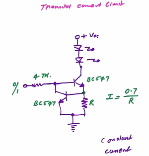
Overall, the circuit provides a robust solution for current limiting, with features that enhance usability and safety, making it suitable for a variety of electronic projects.This circuit allows you to set a limit on the maximum output current available from your PSU. It`s very useful when you power-up a project for the first time - or carry out a soak-test. By setting an upper limit on the current available from your PSU - you can protect both your power supply - and any device connected to it. It offers a simple and cheap alternative to the Current Limiting Power Supply The basic circuit is shown in the first schematic. The two diodes fix the voltage on the base of the Power Transistor at about 1v4. This means that the voltage across R2 is fixed at about 0v7. If R2 is 10 ohms, then the maximum emitter current is (0v7 G ½10) about 70mA. Since the collector current is always more or less equal to the emitter current - you cannot draw more than 70mA from the output terminals.
If you try to do so - the output voltage will fall. I used a BD131 because that was what I had available. However, any NPN Power Transistor with a similar - or better - spec should work fine. I had no special reason for chosing a 70mA maximum. If you want to set a different current limit - change the value of R2. The formula is in the diagram. Always remember that if you increase the current - you`ll also increase the watts. The second schematic has a couple of added features. If you don`t want to use a voltmeter on the output - use an LED instead. If the output voltage falls - the LED will dim or extinguish completely. This is enough to let you know that the load on the output is excessive. Where the Current Limiter is to be left unattended for any length of time - say during a soak-test - the Buzzer is useful. Should a problem develope - and the output voltage fall by 2-volts or more - the circuit will sound the alarm.
The layout provided is for the second schematic - but it`s flexible. If you don`t want the LED feature - just leave out the LED and R3. If you don`t want the alarm feature - leave out D3, D4, D5, R4, R5 & Q2. The heatsink is a folded strip of aluminium about 2mm thick, 6cm long and 3cm tall. If you increase significantly the maximum current available from the limiter circuit - you`ll probably need to increase the size of the heatsink as well. The Support Material for this circuit includes a detailed guide to the construction of the circuit-board, a parts list, a complete circuit description and more
🔗 External reference
Related Circuits
This circuit generates a constant current, constant voltage switched-mode power supply (SMPS). It is designed to efficiently charge a battery using a constant current, constant voltage approach. The circuit operates as a constant current, constant voltage SMPS, which is crucial...
This is a constant current source LED driver. When the upper NPN transistor is activated by a voltage through a 4.7kΩ resistor, the LED lights up. It is assumed that the lower NPN transistor is absent. The current flowing...
An alternative method for utilizing operational amplifiers (op-amps) to regulate a power supply is illustrated below. The power transformer necessitates an additional winding to provide the op-amps with a bipolar voltage of +/- 8 volts. This negative voltage is...
A constant-voltage active load can function as a battery during the charge cycle. The load voltage can be adjusted from 5 to 35V using potentiometer PV, simulating batteries with voltages ranging from 6 to 32V. In the testing of...
This is an adjustable constant current regulator circuit. This circuit can be used in a bench power supply to prevent the circuits that are tested from being damaged. The adjustable constant current regulator circuit is designed to provide a stable...
The LTC6101 operational amplifier can be utilized for high-voltage current monitoring and sensing. This circuit is capable of sensing current in a 500-volt system. Here is the schematic diagram. The LTC6101 is a high-voltage current sense amplifier designed specifically for...