
EPSON PHOTO 830U printer power circuit
The EPSON PHOTO 830U printer power circuit is designed to efficiently convert high-voltage AC input into stable low-voltage DC outputs suitable for the printer's operation. The use of a switching power supply allows for compact design and high efficiency, as it minimizes energy loss compared to linear power supplies.
The initial stage of the circuit involves the AC input, which is protected by a fuse to prevent overcurrent situations that could damage the circuit. The mutual inductance filter serves to reduce electrical noise and ripple from the AC line, ensuring that the rectification process operates smoothly.
The bridge rectifier, consisting of four diodes arranged in a specific configuration, effectively converts the AC waveform into a pulsating DC signal. The smoothing effect of the electrolytic capacitor (C1) is crucial, as it stabilizes the output voltage by filtering out fluctuations, thus providing a reliable DC voltage for the subsequent stages.
The switching transformer (T1) plays a pivotal role in the circuit. It not only steps down the voltage but also isolates different sections of the circuit, enhancing safety and performance. The feedback mechanism within the transformer allows for self-regulation of the oscillation frequency, ensuring that the output remains stable under varying load conditions.
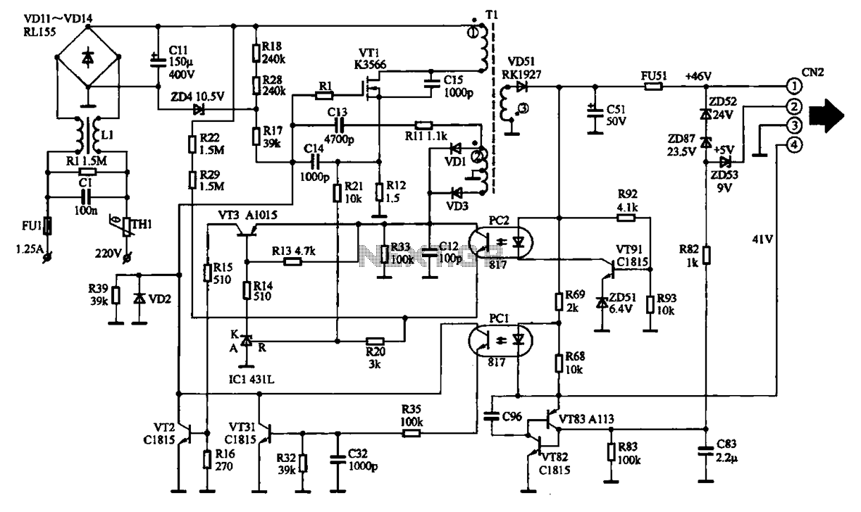
The output from the transformer is then rectified and filtered again to obtain the final DC output voltages. These outputs are essential for powering various components on the main circuit board, ensuring that the printer operates efficiently and reliably during its printing tasks. Overall, this power circuit exemplifies the principles of modern power electronics, integrating multiple functions into a compact and efficient design.EPSON PHOTO 830U printer power circuit It shows EPSON PHOT0 830U printer power supply circuit, which belongs to the switching power supply. In normal operation, the power suppl y input socket will 2,20V AC supply circuit board. After 220V AC fed through the first fuse and mutual inductance filter. After a 220V AC, filtered and fed by a bridge rectifier circuit composed of four rectifier diodes, the 220V AC into a DC voltage of about 300 V, and then supplied to both ends of the electrolytic capacitor CI1. The electrolytic capacitor voltage is 400 V, which is mainly used for 30V DC voltage filtering. After a filter, a DC voltage of 30V Panther gave switching transformer Tl, opening off the transformer Tl and the other end connected to the drain of the switching transistor VT1.
30V DC voltage via the starting resistor R18 after switching to a field effect transistor gate should provide starting voltage. This voltage is applied to the gate field effect transistor switch after which they begin to have a current flows in the primary winding current will be switching transformer.
In the switching transformer, there is a positive feedback winding, an electric current is immediately generates a sensing signal such that the switching FET into oscillation, after the oscillation is generated in the primary winding of the transformer in the switching of the high frequency oscillating current, will produce the corresponding secondary induced current frequency. Switching transformer secondary output voltage through the rectifier filter, the output lead two DC output voltage and to the main circuit board.
Related Circuits
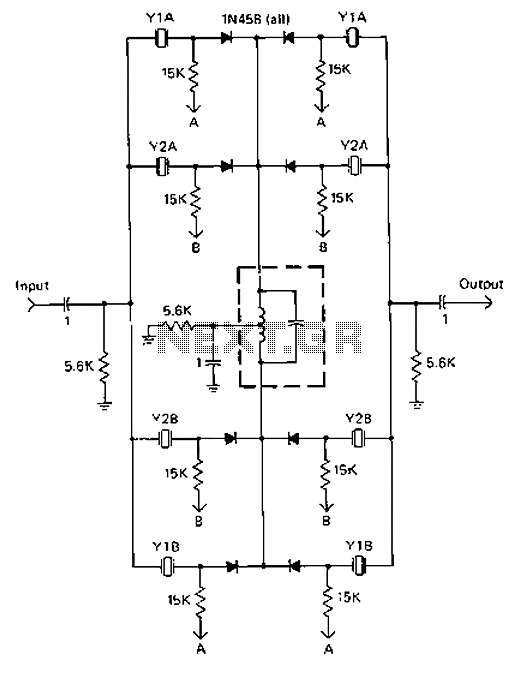
A 9-12V DC power supply is connected to control point A or point B for an amateur communication receiver IF amplifier, offering two distinct options. The power frequency is set at 455 kHz with a bandwidth of 500 Hz....
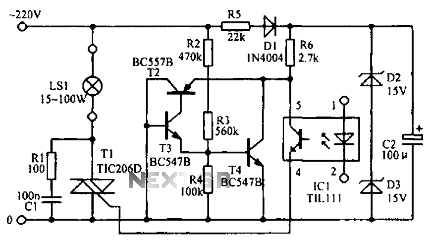
The circuit diagram illustrates the LED signal amplification. The LED signal amplification circuit is designed to enhance the output signal from an LED, allowing it to drive larger loads or to be interfaced with other electronic components effectively. The primary...
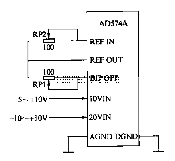
The AD574A is a high-performance 12-bit successive approximation analog-to-digital (A/D) converter that can interface directly with an 8 or 16-bit microprocessor bus. The input to the AD574A can be either unipolar or bipolar. The unipolar analog input voltage range...

The inverting input is maintained at a low level via a 10K resistor when the circuit is powered on but not in use. During measurement activities, including calibration measurements where the input is floating, this resistor is disconnected. The...
The TPS3803 and TPS3805 families of supervisory circuits offer circuit initialization and timing supervision, mainly for digital signal processors (DSPs) and processor-based systems. The TPS3803G15 device features a fixed-sense threshold voltage (VIT) determined by an internal voltage divider, while...
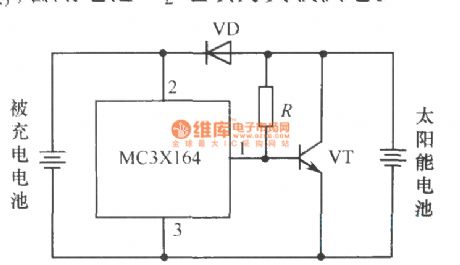
The following circuit illustrates a current-limited solar battery charger circuit diagram. This lead-acid or Ni-Cd battery charger circuit diagram utilizes solar energy to charge a 6-volt, 4.5 Ah rechargeable battery for various applications. It represents a straightforward solar battery...
Warning: include(partials/cookie-banner.php): Failed to open stream: Permission denied in /var/www/html/nextgr/view-circuit.php on line 713
Warning: include(): Failed opening 'partials/cookie-banner.php' for inclusion (include_path='.:/usr/share/php') in /var/www/html/nextgr/view-circuit.php on line 713