
Custom Fan Controller
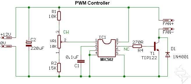
This circuit diagram is designed for controlling the speed of fans in various electronic applications. The key component in this setup is the variable resistor, which serves as a potentiometer to adjust the voltage supplied to the fan motor. This voltage control allows for smooth operation across a range of speeds, providing flexibility in cooling performance based on thermal requirements.
In the modified circuit, the timing capacitor plays a crucial role in determining the response time of the fan speed adjustment. By replacing the 0.1 µF capacitor with a 100 pF capacitor, the circuit achieves a more stable operation without the undesirable noise associated with slower fan speeds. This change is particularly beneficial in environments where noise reduction is essential, such as in home theaters or quiet office spaces.
The design also offers the option for user interaction through manual control. The variable resistor can be mounted directly on the circuit board for straightforward adjustments or can be configured as a remote control unit, allowing users to adjust the fan speed from a distance. This versatility caters to different user preferences and installation scenarios, enhancing the overall usability of the circuit.
When implementing this circuit, it is important to ensure that all components are rated appropriately for the application, particularly the fan motor and the variable resistor, to prevent overheating or electrical failure. Proper thermal management should also be considered, as fan speed control is often critical in maintaining optimal operating temperatures for electronic devices. Overall, this circuit provides an effective solution for fan speed regulation while minimizing noise and offering user-friendly controls.This is the circuit diagram for each individual channel; Note: I replaced the 0. 1 uF timing capacitor with a 100 pF capacitor for better operation, with the 0. 1 uF capacitor in place, the fans would growl when turned down to slower speeds and the 100 pF capacitor resolved that problem. This is the circuit diagram for each individual channel; Note: I replaced the 0. 1 uF timing capacitor with a 100 pF capacitor for better operation, with the 0. 1 uF capacitor in place, the fans would growl when turned down to slower speeds and the 100 pF capacitor resolved that problem. wow, that`s impressive. I have almost no experience with circuitry on that level, so that wouldn`t work too well for me (how do you control that then btw, cause if it`s a knob of some sort, I may look into something like that, how hard would it be to learn) That would be real close to what I`m looking for, if you could add manual knobs, but If not the Zalman would work perfectly.
wow, that`s impressive. I have almost no experience with circuitry on that level, so that wouldn`t work too well for me (how do you control that then btw, cause if it`s a knob of some sort, I may look into something like that, how hard would it be to learn) That would be real close to what I`m looking for, if you could add manual knobs, but If not the Zalman would work perfectly. wow, that`s impressive. I have almost no experience with circuitry on that level, so that wouldn`t work too well for me (how do you control that then btw, cause if it`s a knob of some sort, I may look into something like that, how hard would it be to learn) That would be real close to what I`m looking for, if you could add manual knobs, but If not the Zalman would work perfectly.
It uses a variable resistor to control the fan speed this can either be on-board (as in my case; notice the light blue squares with the slotted white screw at the center) or with a remote (panel mount) potentiometer with a knob. 🔗 External reference
Related Circuits
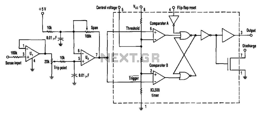
Many applications require analog signals to be sensed and digital signals to be controlled. A way to detect these points is by using a 555 timer in an unconventional configuration. This method will also add hysteresis to the circuit...
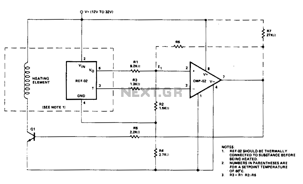
Temperature control is accomplished using the REF-02 +5 V Reference/Thermometer in conjunction with the CMP-02 Precision Low Input Current Comparator. The CMP-02 activates a heating element driver (Q1) whenever the current temperature falls below a predetermined setpoint, which is...
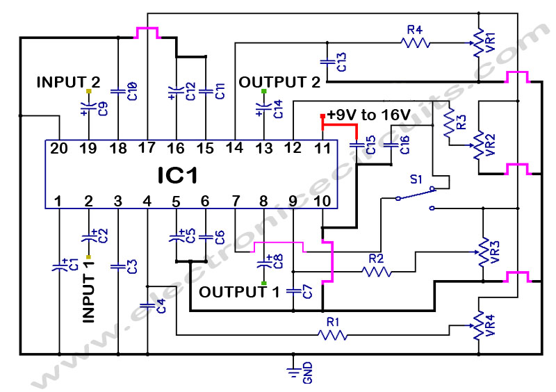
LM1036 Stereo Tone (Bass, Treble, Volume, Loudness, Balance) Controller Circuit. The LM1036 is a DC controlled tone (bass/treble), volume, and loudness controller designed for audio applications. The LM1036 circuit serves as an integrated solution for controlling various aspects of audio...
To achieve greater sensitivity, consider using the 74AC04 or 74HC04 in place of the 74HCU04 for component U1. While the 74AC04 and 74HC04 may offer improved performance over the 74HCU04, it is important to note that the frequency response...
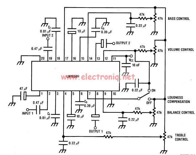
This volume controller equalizer electronic project is designed using the LM1036 DC tone volume controller, featuring a volume and balance circuit for stereo applications. The four control inputs of the LM1036 volume controller enable the control of bass, treble,...

A simple frequency meter or frequency counter circuit featuring an LCD display and an AVR microcontroller. This includes a DIY schematic circuit diagram and embedded C code. The frequency meter circuit is designed to measure the frequency of input signals...